
Vehicle with high voltage line

a high-voltage line and vehicle technology, applied in the field of vehicles, can solve the problems of affecting the service life of the vehicle, so as to prevent the disconnection of the high-voltage line

Inactive Publication Date: 2005-09-22
TOYOTA JIDOSHA KK
View PDF7 Cites 52 Cited by
  • Summary
  • Abstract
  • Description
  • Claims
  • Application Information

AI Technical Summary

Benefits of technology

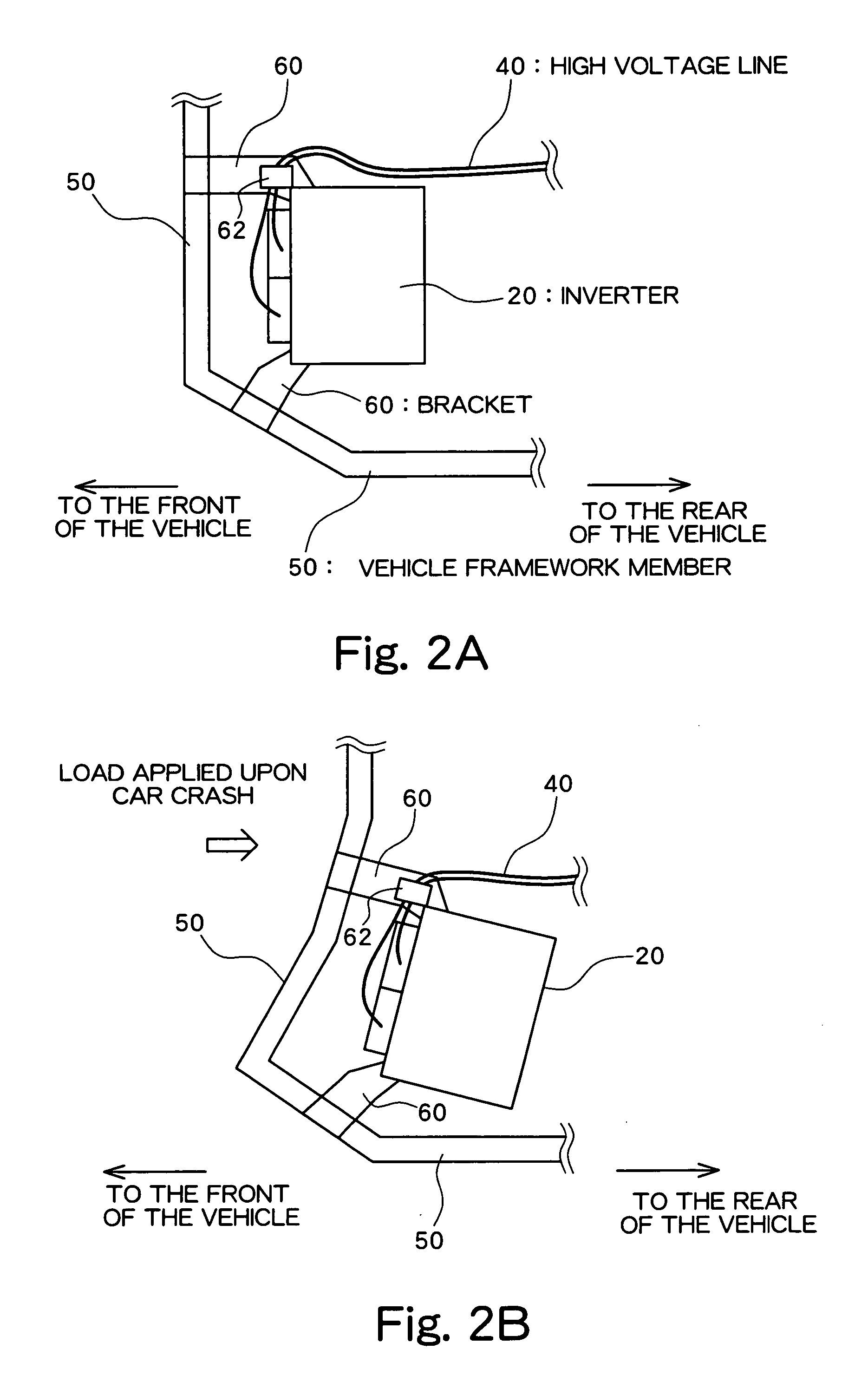
[0010] In this structure, the framework member and the fastening member are made by a rigid material, such as a metal. According to this structure, the high voltage line is attached to the high voltage unit by the same fastening member as used for attaching the high voltage unit. Therefore, when the framework member is deformed due to the car crash and the high voltage unit is deformed accordingly, the high voltage line is moved to follow the deformation of the framework member and the displacement of the high voltage unit. Thus, it is possible to prevent the high voltage line from being sandwiched between the high voltage unit and the framework member. In other words, the disconnection of the high voltage line can be avoided.
[0012] In accordance with the present invention, it is possible to prevent the disconnection of the high voltage line.

Problems solved by technology

In the event of a vehicular accident, there is a possibility that such a high voltage line may become a voltage hazard and cause electrocution.
For example, it can be anticipated that, in the event of a car crash, the connection between the high voltage line and the inverter may be broken so that a high voltage is applied to the body of the vehicle, and, if someone touches the body of that vehicle, he or she may be electrocuted or suffer an electric shock.
In addition to separation of the high voltage line from the terminals, an electric shock may also occur because of the disconnection of the high voltage line itself.
For example, the high voltage line may be sandwiched and disconnected between the inverter and the framework of the vehicle, and the disconnected part may contact the framework to create an electric shock hazard.

Method used


Image

  • Vehicle with high voltage line
  • Vehicle with high voltage line
  • Vehicle with high voltage line

Examples


Embodiment Construction

[0015] A preferred embodiment of the present invention will be described below with reference to the attached drawings.

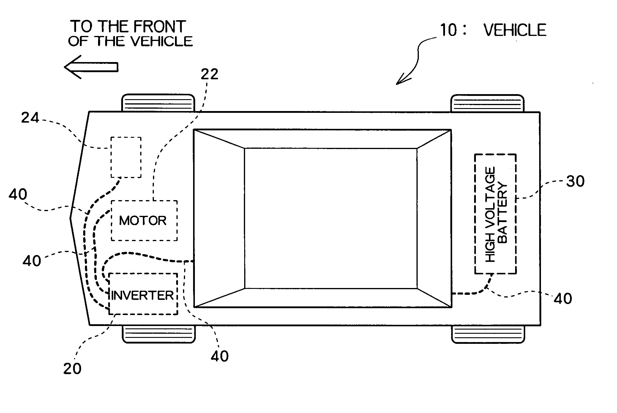
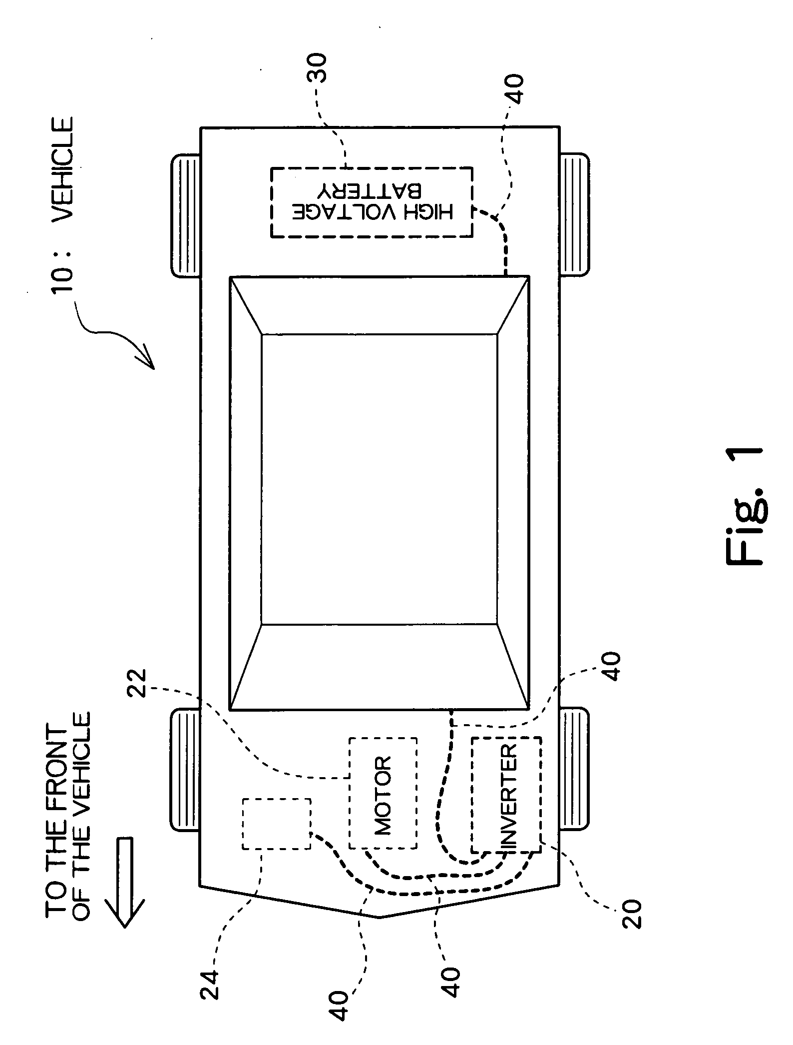
[0016]FIG. 1 is an overall schematic view of a preferred embodiment according to the present invention.

[0017] A vehicle 10 utilizes a motor 22 as the motive power source. For example, the vehicle 10 may be an electric vehicle driven by the motor 22, or a hybrid vehicle driven by the motor 22 together with an engine which is not shown. The vehicle 10 includes a high voltage battery 30 which stores electric power to drive the motor, and an inverter 20 which supplies drive signals to the motor 22, and a high voltage line 40 which transmits electric power to the inverter 20 from the high voltage battery 30. The inverter 20 is arranged in an engine room (engine compartment) which is located in the front part of the vehicle. It is noted that the engine is not always provided in the engine room, as the electric vehicle does not require the engine for the motive power use...


PUM


Abstract

As a framework member 50 of a vehicle deforms, a bracket attached to the framework member 50 also deforms. An inverter 20 which is attached to the framework member 50 via a bracket 60 also deforms. Thus, following the deformation of the framework member 50 of the vehicle, the bracket 60 and the inverter 20 deform accordingly to result in a rather small amount of relative deformation among the framework member 50, the bracket 60, and the inverter 20. In addition, a high voltage line 40 attached to the bracket 60 also deforms following the deformation of the bracket 60. Therefore, even in the event of an accident, the high voltage line 40 can be secured in a space reserved between framework member 50 and inverter 20, which significantly reduces the possibility of disconnection of the high voltage line 40.

Description

BACKGROUND OF THE INVENTION [0001] 1. Filed of the Invention [0002] The present invention relates to a vehicle which uses a motor as the motive power source, and particularly to a vehicle with high voltage lines. [0003] 2. Description of the Related Art [0004] Vehicles driven by a motor have been known, such as an electric vehicle which uses a motor alone as the motive power source and a hybrid vehicle which uses both a motor and an engine as the motive power source. In both electric vehicles and hybrid vehicles, a motor is connected to an inverter which is, in turn, connected to a high voltage battery. In other words, such vehicles are made to run by feeding electric power to the inverter from the high voltage battery and supplying a drive signal from the inverter to the motor in response to the running status of the vehicle, with a high voltage line connecting the inverter to the high voltage battery. [0005] In the event of a vehicular accident, there is a possibility that such a ...

Claims


Application Information

Patent Timeline
IPC IPC(8): B62D25/08B60K1/04B60L11/18B60L15/00B60R16/02B60R16/04H02G1/06
CPCB60R16/04B60L3/0007
Inventor YAMAFUJI, TAKAHIRO
Owner TOYOTA JIDOSHA KK
Learn More