Grinder pump tank

a technology of grinder pump and grinder tank, which is applied in the direction of sewer system, solid separation, construction, etc., can solve the problems of fiberglass grinder pump station denting and chipping, damage may not be ascertainable, and the cost of fiberglass is relatively high, so as to improve structural integrity, improve structural integrity, and simplify manufacturing

Inactive Publication Date: 2005-09-22
STROHECKER JAMES R +1
View PDF2 Cites 2 Cited by
  • Summary
  • Abstract
  • Description
  • Claims
  • Application Information

AI Technical Summary

Benefits of technology

[0017] It is, therefore, an object of the present invention to provide an improved HDPE grinder pump tank comprising five primary components, four of which are butt fused locally and amalgamated into one piece to avoid imperfections, thereby improving structural integrity.
[0018] It is another object to provide an improved grinder pump tank as described above that utilizes repetitive sections for economy of manufacture, and specifically comprising five primary components of which four are butt fused locally and amalgamated into one piece to avoid imperfections, thereby improving structural integrity.
[0019] It is still another object to provide an improved HDPE grinder pump tank that simplifies manufacture, increases strength, all at a reasonable cost.
[0020] According to the present invention, the above-described and other objects are accomplished by providing an improved sewage grinder pump tank

Problems solved by technology

For example, fiberglass is a relatively expensive material.
Fiberglass grinder pump stations are subject to denting and chipping as the result of shipment or installation.
Such damage may not be ascertainable until after installation is complete and leaking begins.
Fiberglass also has a limited ability to withstand the abras

Method used


Image

  • Grinder pump tank
  • Grinder pump tank
  • Grinder pump tank

Examples


Embodiment Construction

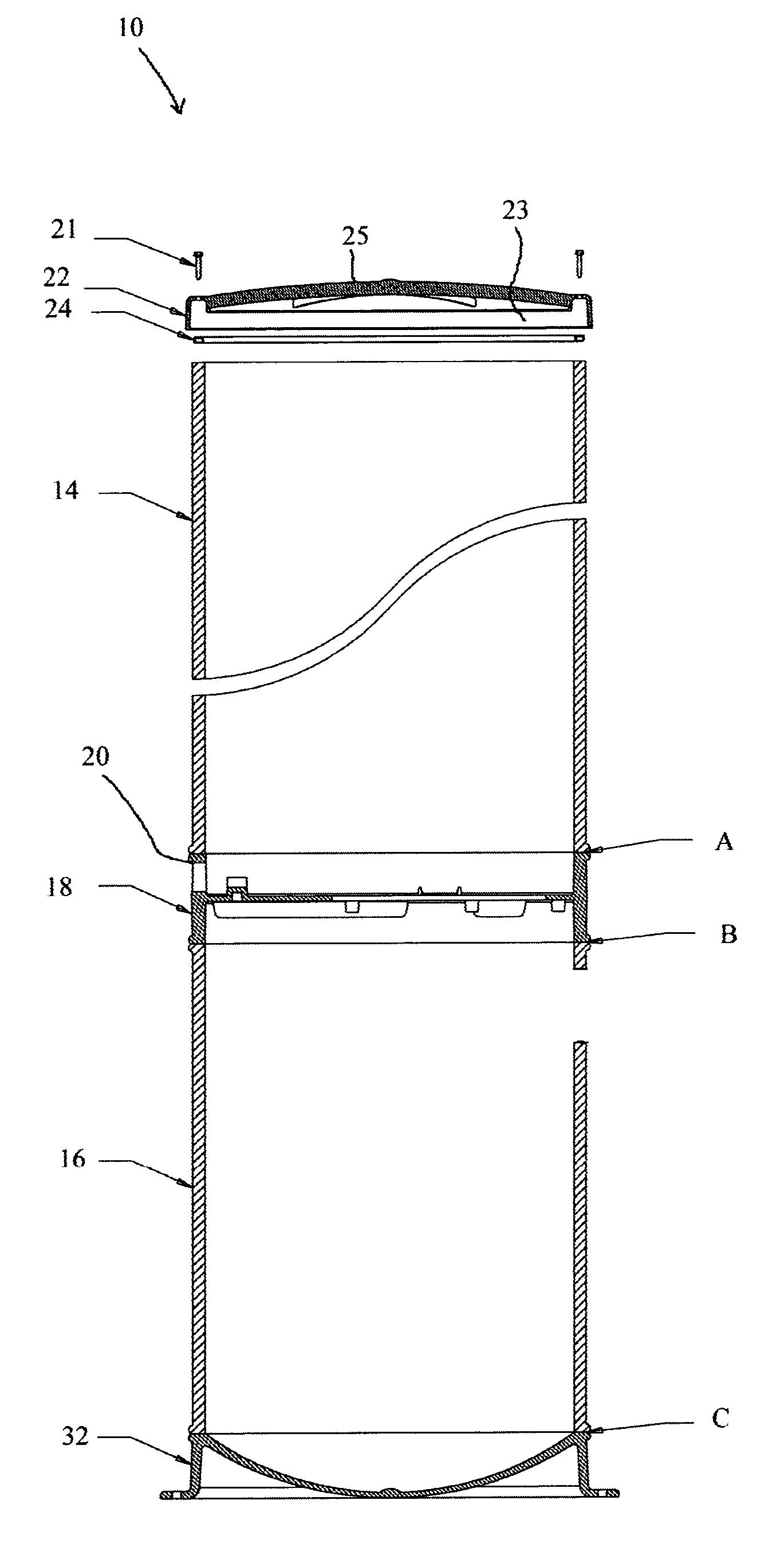
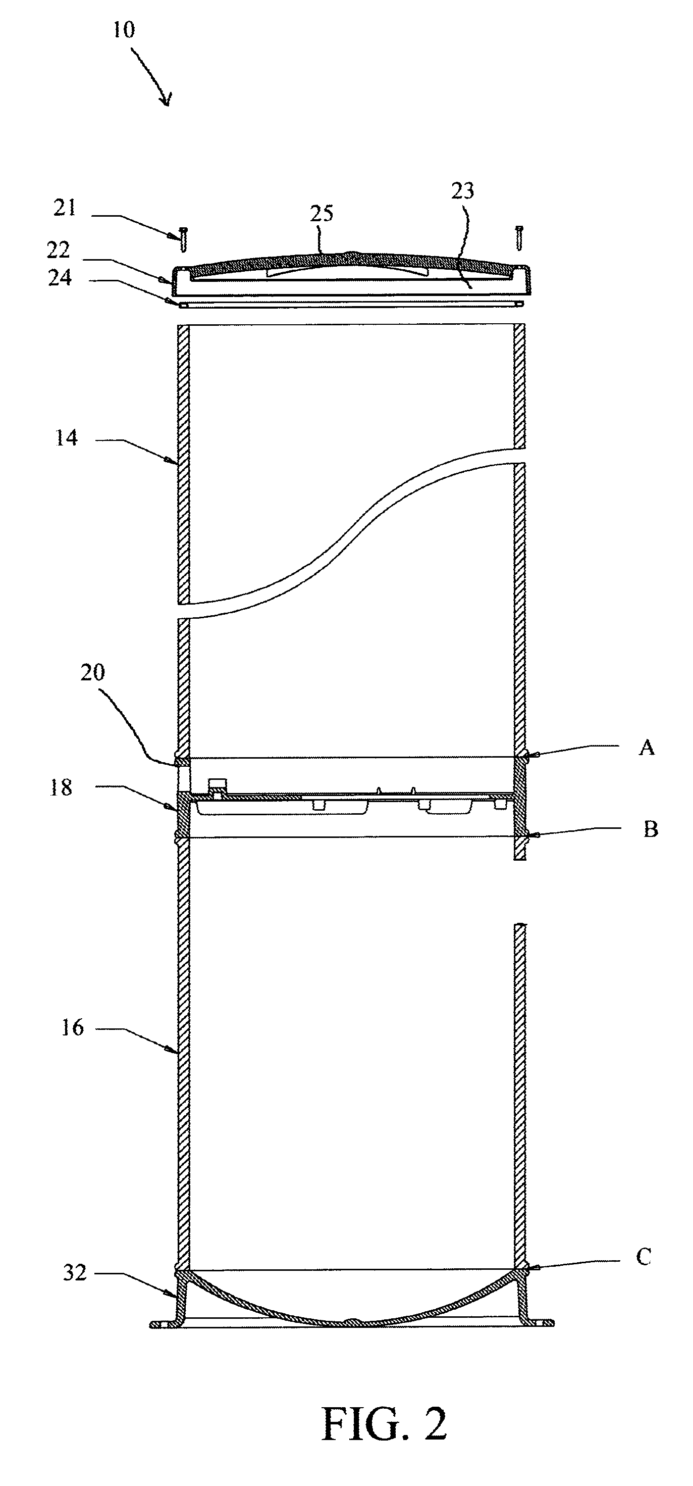
[0034]FIG. 2 is a cross-section of a grinder pump tank 10 according to the present invention, and FIG. 3 is a side perspective view of the grinder pump tank 10 as in FIG. 1.

[0035] Grinder pump tank 10 includes a lid assembly 22, an upper tank portion 14, a pump platform section 18, a lower tank portion 16, and a base 32. The upper tank portion 14, lower tank portion 16 and lid assembly 22 are injection molded structural foam HDPE parts. Extending through the side wall of pump platform section 18 is an outlet opening 20 through which sewage leaves the grinder pump station 10. FIG. 4 is a top view, and FIG. 5 is a side cross-section, respectively, of the lid assembly 22. Lid assembly 22 further comprises a molded HDPE tank lid, concave inward, and having a recessed annular collar 23 for mounting atop the upper tank portion 14 via a rubber O-ring 24. Stainless steel tamper proof screws 21 are used to anchor the lid assembly 22 in place.

[0036]FIG. 6 is a top view, and FIG. 7 is a side...


PUM


Abstract

An improved sewage grinder pump tank inclusive of an upper tank portion formed as a cylindrical section of DR 32.5 HDPE, a lid assembly covering the upper tank portion, a lower tank portion similar to the upper tank portion, a pump platform section in communication with the upper tank portion and lower tank portion and forming a platform there between for mounting a grinder pump, and a base formed as a concave molded section for mating with the lower tank portion. The pump platform section is butt fused between the upper tank portion and the lower tank portion, and the base is butt fused to the open end of the lower tank portion. The butt fusion amalgamates the parts into one piece and avoids imperfections, thereby improving structural integrity. In addition, the grinder pump tank simplifies installation, and reduces cost.

Description

CROSS-REFERENCE TO RELATED APPLICATIONS [0001] The present application derives priority from U.S. Provisional Patent Application No. 60 / 399,468 filed: Jul. 29, 2002.BACKGROUND OF THE INVENTION [0002] 1. Field of the Invention [0003] The present invention relates to sewage grinder pumps and, more particularly, to an improved tank assemblage for a grinder pump station and method for making the same. [0004] 2. Description of the Background [0005] Sewage grinder pump stations are well-known, as exemplified in U.S. Pat. No. 5,562,254 issued to Sleasman et al. As seen in FIG. 1 herein (taken from the '254 patent), a typical grinder pump station 10 is positioned substantially vertically in the ground. Grinder pump station 10 includes a lid assembly 22, an upper tank portion 14, a pump platform section 18, a lower tank portion 16, and a base 32. Extending through side wall 17 of pump platform section 18 is an inlet opening 20 through which sewage enters grinder pump station 10, and a discha...

Claims


Application Information

Patent Timeline
IPC IPC(8): B02C23/36E03F5/22
CPCE03F5/22
Inventor STROHECKER, JAMES R.HALL, ALAN B.
Owner STROHECKER JAMES R
Why Eureka
Try Eureka