
Phosphor material and white light-emitting device using the same

a technology of white light and phosphor material, which is applied in the direction of luminescent compositions, energy-saving lighting, sustainable buildings, etc., can solve the problems of difficult manufacture of short-wavelength blue led, and achieve the effect of improving efficiency and facilitating the use of blue led

Inactive Publication Date: 2005-09-22
LITE ON TECH CORP
View PDF5 Cites 10 Cited by
  • Summary
  • Abstract
  • Description
  • Claims
  • Application Information

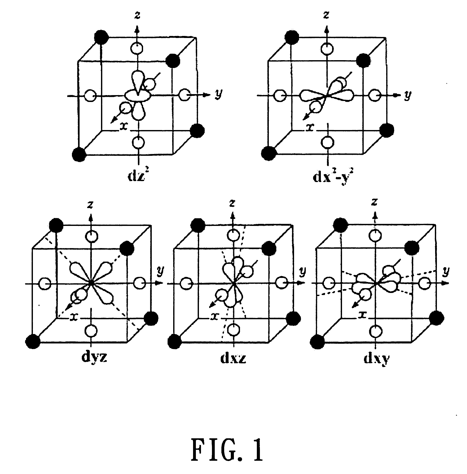
AI Technical Summary

Benefits of technology

[0010] The short-wavelength blue LED has more difficult manufacture than the long-wavelength blue LED. The wavelength-adjustable property of the phosphor according to the present invention can advantageously facilitate the use of blue LED in long-wavelength regime. For example, the phosphor can be advantageously excited by blue LED of 470 nm with higher efficiency instead of 460 nm blue LED.
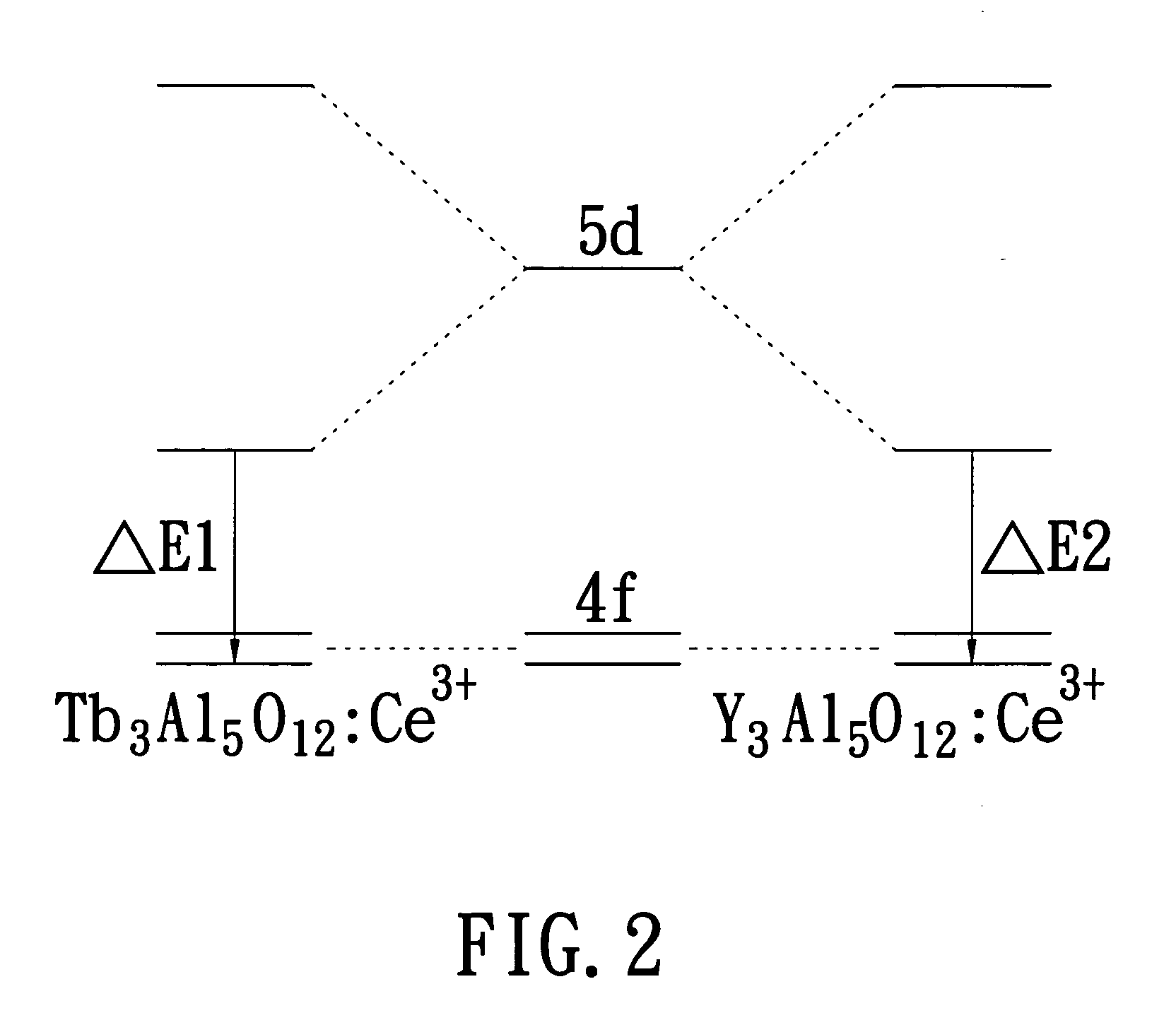
[0011] In the present invention, the luminescent wavelength of phosphor is adjusted by modulating the crystal field of the host matrix of used phosphor instead of changing the amount of hetero ions. The added amount of the hetero ions is too small to be precisely controlled. On the contrary, the process of the present invention is simpler and more stable.

Problems solved by technology

The short-wavelength blue LED has more difficult manufacture than the long-wavelength blue LED.

Method used


Image

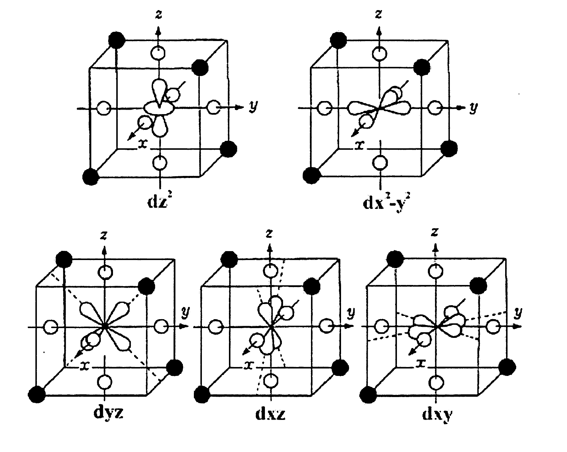
  • Phosphor material and white light-emitting device using the same
  • Phosphor material and white light-emitting device using the same
  • Phosphor material and white light-emitting device using the same

Examples


example 1

A. EXAMPLE 1

[0030] 1. Preparing mixture for forming a composition having a stoichiometry of (Y1.80Tb1.20Ce0.05)Al5O12 by mixing and grinding Y(NO3)3·6H2O of 3.1750 g, Al(NO3)3·9H2O of 8.6400 g, Ce(NO3)3·6H2O of 0.1000 g and Tb4O7 of 8.6400 g.

[0031] 2. Placing thus-produced mixture in a crucible and heating the mixture for calcination in air at 1000° C. with a heating rate of 5° C. / min for 24 hours and followed by cooling down at a cooling rate of 5° C. / min to form intermediate powders.

[0032] 3. Grinding the calcined powder and then placing the calcined powder again in the crucible for sintering in air for 24 hours with temperature ramp and drop of 5° C. / min.

[0033] 4. Placing the sintered powder in a H2 / N2 (5% / 95%) reductive ambient at 1500° C. for 12 hours for reduction. This reduces Ce4+ to Ce3+. It is noted that this step, which can improve light brightness, is optional.

example 2

B. EXAMPLE 2

[0034] 1. Preparing mixture for forming a composition having a stoichiometry of (Y2.375Tb0.625 Ce0.05)Al5O12 by mixing and grinding Y(NO3)3·6H2O of 4.1897 g, Al(NO3)3·9H2O of 8.6400 g, Ce(NO3)3·6H2O of 0.1000 g and Tb4O7 of 0.2836 g.

[0035] 2. Placing thus-produced mixture in a crucible and heating the mixture for calcination in air at 1000° C. with a heating rate of 5° C. / min for 24 hours and followed by cooling down at a cooling rate of 5° C. / min to form intermediate powders.

[0036] 3. Grinding the calcined powder and then placing the calcined powder again in the crucible for sintering in air for 24 hours with temperature ramp and drop of 5° C. / min.

[0037] 4. Placing the sintered powder in a H2 / N2 (5% / 95%) reductive ambient at 1500° C. for 12 hours for reduction.


PUM

PropertyMeasurementUnit
domination wavelengthaaaaaaaaaa

Abstract

A white light-emitting device comprising a blue-violet or blue LED and a phosphor material capable of emitting a yellow-green to orange-yellow light upon excitation by the light emitted by the LED. The light from the LED and the phosphor material are mixed in an appropriate ratio to produce a white light. The phosphor material has a general formula (YxMyCez)Al5O12, where x+y=3, x, y≠0, 0.5>z>0, and M is selected from the group consisting of Tb, Lu, and Yb, with (YxMy)Al5O12 serving as a host and Ce as an activator. By changing the composition of the metal elements in the host, the crystal field is modulated to thereby alter the energy level of the excited state to which the activator is transferred upon irradiation by a specific wavelength of light, leading to the change in the emitting wavelength of the phosphor material.

Description

FIELD OF THE INVENTION [0001] The present invention relates to high-brightness white light-emitting device, especially to a high-brightness white light-emitting device with a purple-blue light or blue light emitting diodes in combination with suitable phosphor to provide white light. BACKGROUND OF THE INVENTION [0002] It is known that the white light is mixed light of different colors. The white light, which is sensed by human eye as white color, at least includes two or more colors of light having different wavelengths. For example, when human eye is stimulated, at the same time, by the Red, Green, and Blue colors of light, or by blue light and yellowish light, a white color is sensed. Accordingly, there have been three major approaches to the formation of white light for now. The first is using R / G / B LEDs. By controlling the current passing the LED to generate white light. The second is using yellow / blue LEDs to generate white light. These two prior art methods has a common drawba...

Claims


Application Information

Patent Timeline
Patent Type & Authority Applications(United States)
IPC IPC(8): C09K11/77H01L27/15H01L33/50
CPCC09K11/7774Y02B20/181H01L33/502Y02B20/00
Inventor LIU, RU-SHILIN, YI-SHANCHI, LIANG-SHENGWANG, CHIEN-YUAN
Owner LITE ON TECH CORP
Learn More