
Apparatus for forming an asymmetric illumination beam pattern

a technology of asymmetric illumination and apparatus, applied in the field of lighting, can solve the problems of affecting the appearance, affecting the effect of light intensity,

Active Publication Date: 2005-09-22
SIGNIFY HLDG BV
View PDF17 Cites 85 Cited by
  • Summary
  • Abstract
  • Description
  • Claims
  • Application Information

AI Technical Summary

Benefits of technology

The present invention provides an apparatus for creating an asymmetric beam pattern for illumination. The apparatus includes two optical elements that manipulate the illumination in opposite directions, creating an asymmetric beam pattern. This technology can be used in various applications such as lighting, display, and optical communication.

Problems solved by technology

Such hot spots are distracting and aesthetically displeasing.
The problem with this type of system is that over time the surfaces of the walls can be contaminated with dirt or debris due to water ingress, for example.
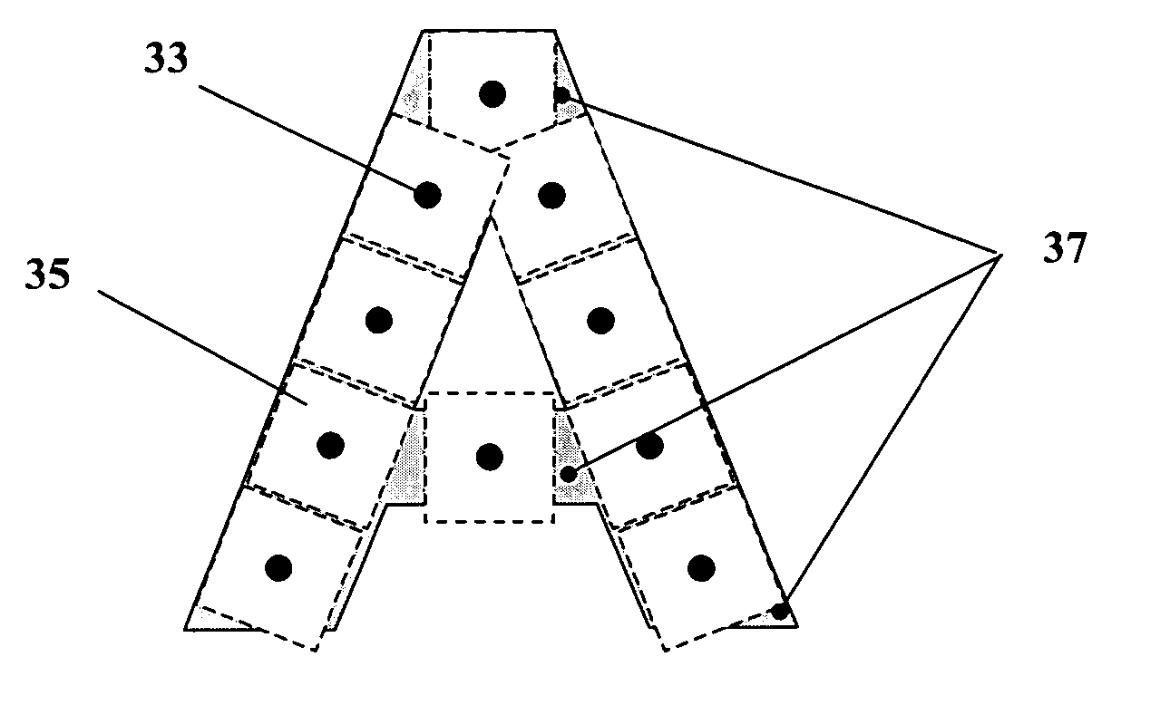
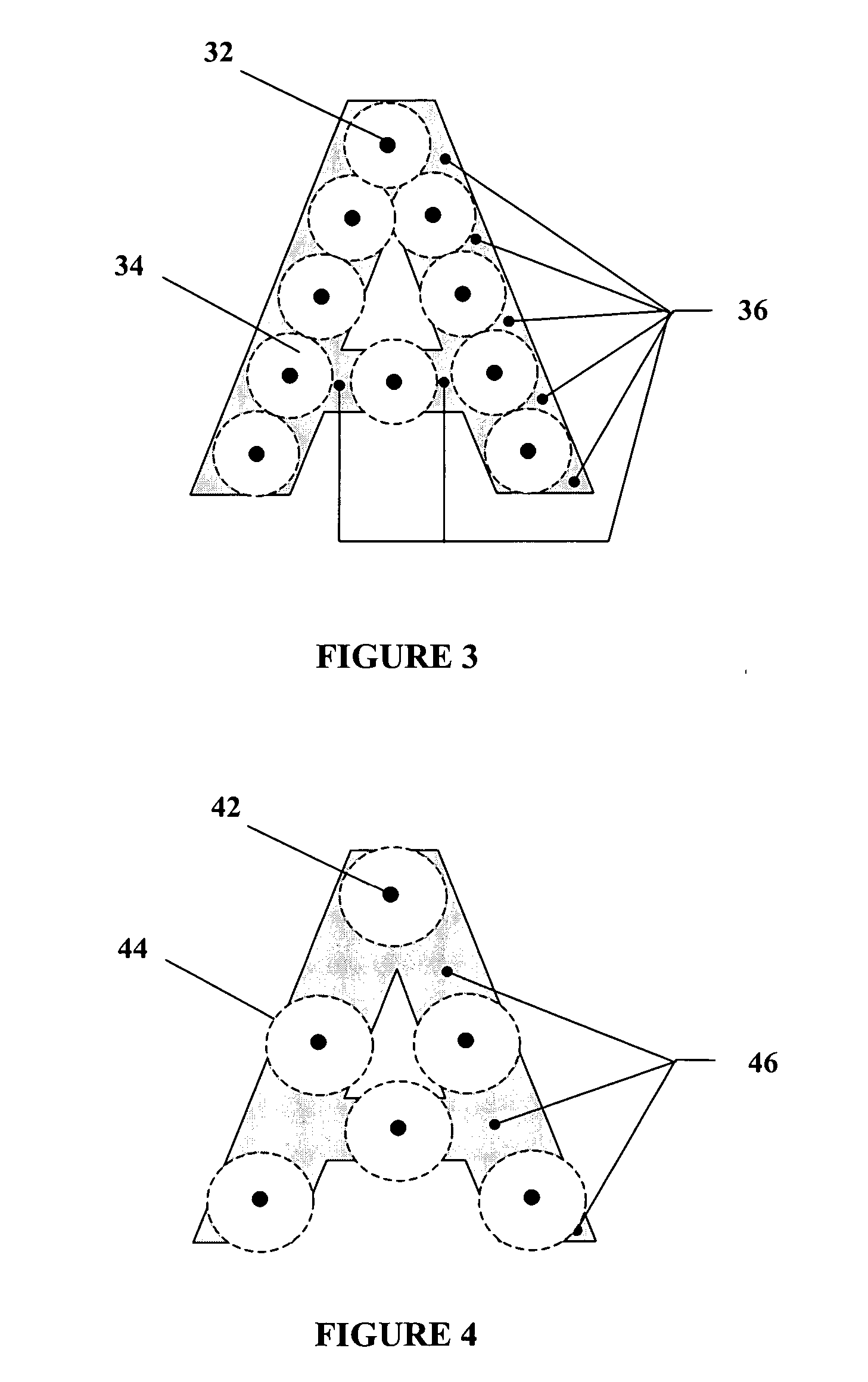
When these LEDs are positioned within a channel letter application, they typically do not provide sufficient uniformity of illumination for the entire channel letter, thereby resulting in dark regions 36.
In order to reduce the size of these dark regions, the LEDs can be closely spaced together, however this closer proximity of the LEDs may not be desired.
Furthermore, when high flux LEDs are used for channel letter applications, typically fewer LEDs are used to illuminate a channel letter due to the higher level of irradiation generated by these devices.
In addition, for narrow channel letters, as is common with letters formed using serif fonts, for example, it can be difficult to fill the narrow regions of this type of letter with light due to its tight geometry as illustrated by locations 30 in FIG. 5.
However, this configuration typically does not provide sufficient light to the narrow regions of channel letters.
These optical configurations however, do not provide sufficient light or illumination to areas with tight geometries, for example, however this product may be used in a light grazing application.
This configuration can pose a challenge as most optics are designed to distribute light symmetrically around at least one axis, resulting in wasted light that does not reach the surface to be illuminated.
This solution however, is not optimal as it creates a non-uniform wash of light that can result in a hot spot located at the centre axis of the beam distribution pattern.

Method used


Image

  • Apparatus for forming an asymmetric illumination beam pattern
  • Apparatus for forming an asymmetric illumination beam pattern
  • Apparatus for forming an asymmetric illumination beam pattern

Examples


Embodiment Construction

Definitions

[0047] The term “light-emitting element” is used to define any device that emits radiation in the visible region of the electromagnetic spectrum when a potential difference is applied across it or a current is passed through it, for example, a semiconductor or organic light-emitting diode (LED or OLED, respectively) or other similar devices as would be readily understood. It would be obvious to one skilled in the art that elements that emit other forms of radiation such as infrared or ultraviolet radiation may also be used if desired in the present invention in place of or in combination with light-emitting elements.

[0048] The term “beam angle” is used to define an angle which is equivalent to twice the angle between the emitted radiation and the plane normal to the exiting surface at which the intensity of the light source is one-half of its intensity at the plane normal.

[0049] Unless defined otherwise, all technical and scientific terms used herein have the same mea...


PUM


Abstract

The present invention provides an apparatus for forming an asymmetric illumination beam pattern that can be advantageous when illuminating channel letters in addition to enabling the creation of cove lighting, as well as other applications benefiting from asymmetric illumination patterns. The apparatus comprises one or more light-emitting elements for creating the illumination. A first optical element is operatively associated with each of the light-emitting elements and provides a means for manipulating the illumination in a first direction. A second optical element is operatively associated with predetermined light-emitting elements and provides a means for manipulating the illumination in a second direction. Upon the interaction of the illumination with both the first and second optical elements, the illumination being created can have an asymmetric beam pattern.

Description

INCORPORATION BY REFERENCE [0001] The present application claims the benefit of U.S. provisional patent application No. 60 / 547,437, filed Feb. 26, 2004, and U.S. provisional patent application No. 60 / 557,394, filed Mar. 30, 2004, both of which are hereby incorporated herein by reference.FIELD OF THE INVENTION [0002] The present invention relates to the field of lighting and more specifically to forming an asymmetric illumination beam pattern of light created by light-emitting elements. BACKGROUND [0003] Channel letters are used to provide signage for buildings, shopping malls, and the like where it is desirable that the signage comprises illuminated letters or any other shapes that are easily seen, even at great distances, day or night. Each channel letter generally comprises an enclosure usually a metal box, having a rear surface which is positioned against a raceway, or the wall of a building, on which the signage is mounted and a plurality of sides which define the figuration of ...

Claims


Application Information

Patent Timeline
Patent Type & Authority Applications(United States)
IPC IPC(8): F21S4/00F21V5/00F21V5/04F21V5/08F21V7/00F21V7/09F21V13/02F21V13/04G02B17/06G02B17/08G09F9/313G09F9/33G09F13/22H01L27/15
CPCF21S4/003F21V5/002F21V5/045F21V7/0025F21V7/0091F21V7/09F21V7/06F21Y2101/02G09F9/313G09F9/33G09F13/22G02B19/0066G02B19/0028F21V13/02F21S4/20F21Y2115/10
Inventor KAN, PETER
Owner SIGNIFY HLDG BV
Learn More