Electrode for electron gun and electron gun using same

a technology of electron gun and electron gun, which is applied in the manufacture of electrode systems, electric discharge tubes/lamps, and tubes with screens, etc., can solve the problems of difficult to orient carbon nanotubes in one direction, and difficult to achieve high-quality electron beams. , to achieve the effect of small work function, excellent stability and high controllability

Inactive Publication Date: 2005-09-22
MITSUBISHI PENCIL CO LTD
View PDF10 Cites 0 Cited by
  • Summary
  • Abstract
  • Description
  • Claims
  • Application Information

AI Technical Summary

Benefits of technology

[0009] It is therefore an object of the present invention to provide an electrode for an electron gun and an electron gun using same which uses a carbonaceous material having a small work function and exhibiting excellent stability and which permits orientation to be highly controlled and can be manufactured at a low cost.
[0023] In the present invention, in order to obtain good thermal resistance at high temperature, the carbonization processing by firing is carried out in an inert atmosphere or in vacuum up to temperature that is higher than the usage temperature as an electron emitter by 260° C.˜500° C., preferably by about 300° C., thereby permitting more stable characteristics for electron emission and longer useful life to be achieved with a lower consumption of electric power.
[0024] In the carbonaceous electrode used for an electron gun according to the present invention, the amorphous carbon which is obtained by carbonization of a polymer resin having good moldability contains edge portion of graphite, carbon nanotubes, or carbon nanofibers having excellent electron emissivity which are homogeneously oriented in one direction to form a composite body of amorphous carbon and graphite, carbon nanotubes, or carbon nanofibers. By thus forming a composite body, the edge portion of graphite or sharp pointed form of carbon nanotubes or carbon nanofibers having excellent electron emissivity are exposed evenly and uniformly so that an electrode of any shape can be formed as an electron emitter so as to have a small work function and a low threshold voltage for electron emission. Since it has excellent thermal resistance, rush current is small in repeated use and a stable discharge current can be obtained to permit a long useful life.
[0025] Thus, by using a carbonaceous electrode formed either from a single carbonaceous electrode in the shape of cylinder of circular cross-section, in a rectangular shape of square cross-section, in the shape of a coil, a cone, or a hollow cylinder, or plural carbonaceous electrodes arranged in an array as required, an electron gun having long useful life and high efficiency with low electric power consumption can be realized.

Problems solved by technology

In the above-mentioned method of using screen printing in liquid form, it is difficult to orientate the carbon nanotubes in one direction.
This method has a further disadvantage that blending ratio of carbon nanotube cannot be increased because an increase in viscosity, with an increasing proportion of carbon nanotubes, prohibits screen printing being carried out.
The method using CVD to form a layer of carbon nanotubes directly on a substrate has a disadvantage that it takes too many steps and too much time to be carried out at a reasonable cost.
The same problem arises with a hot cathode type electron gun such as a cathode ray tube (CRT) as with above-mentioned cold cathode type electron gun.

Method used


Image

  • Electrode for electron gun and electron gun using same
  • Electrode for electron gun and electron gun using same
  • Electrode for electron gun and electron gun using same

Examples


example 1

[0030] To a composition consisting of 40 parts of chlorinated vinyl chloride resin (T-741; manufactured by Nippon Carbide Industries Co.) and 20 parts of furan resin (VF303; manufactured by Hitachi Chemical Co.), 40 parts of natural graphite powder (mean particle diameter of 5 μm; manufactured by Nippon Graphite Industries Co.) and 20 parts of diallyl phthalate monomer as a plasticizer were added, dispersed and mixed, and molded in the shape of fine filament by extrusion molding, and then carbonized in a nitrogen gas atmosphere with 1000° C., and further in argon gas atmosphere with 2000° C. to obtain a carbonaceous electrode of 0.2 mm in diameter.

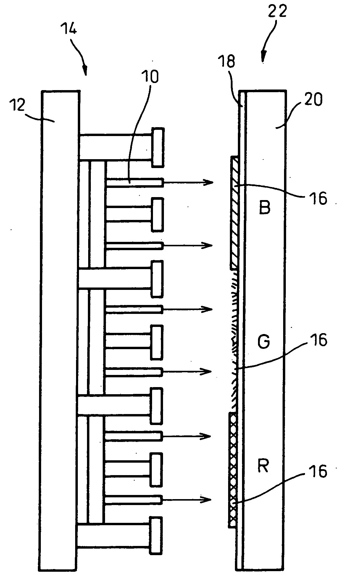
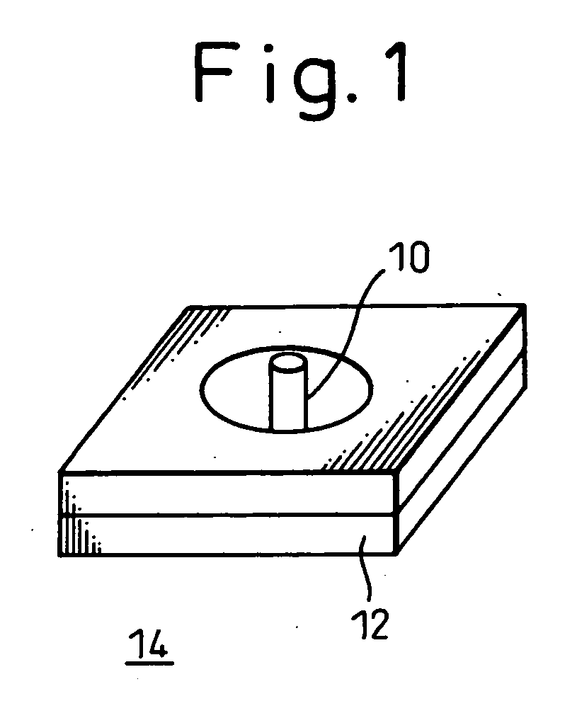
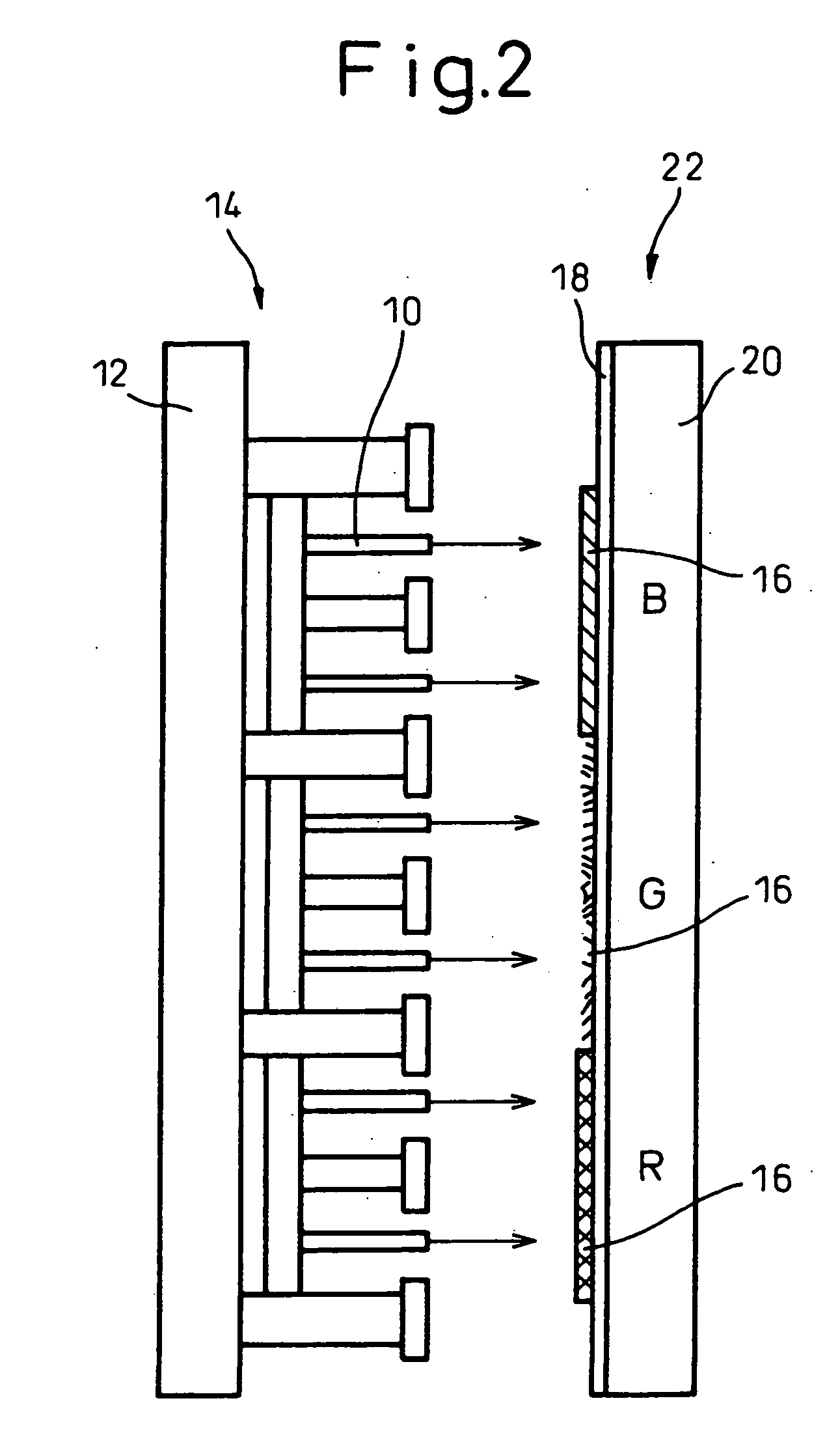
[0031]FIGS. 1 and 2 show the construction of the essential part of a field emission type cold cathode. FIG. 1 shows the basic construction of the unit, and FIG. 2 shows a cross-sectional view of the cathode units arranged in an array.

[0032] As shown in the Figures, the obtained cylindrical carbonaceous electrodes 10 were arranged on an i...

example 2

[0033] To a composition consisting of 50 parts of chlorinated vinyl chloride resin (T-741; manufactured by Nippon Carbide Industries Co.) and 50 parts of carbon nanofiber (mean diameter of 100 nm; manufactured by Showa Denko Co.), 20 parts of diallyl phthalate monomer as a plasticizer were added, dispersed and mixed, and molded by extrusion molding, and then carbonized in nitrogen gas atmosphere with 1000° C., and further in vacuum with 1500° C. to obtain cylindrical carbonaceous electrodes of 0.5 mm in diameter.

[0034] The obtained cylindrical carbonaceous electrodes were used as in Example 1 above, and when an electric field was applied between the two electrodes in vacuum, light emission from the fluorescent body was observed and confirmed all over the surface.

example 3

[0035] To a composition consisting of 50 parts of chlorinated vinyl chloride resin (T-741; manufactured by Nippon Carbide Industries Co.), 25 parts of natural graphite powder (mean particle diameter of 5 μm; manufactured by Nippon Graphite Industries Co.) and 25 parts of carbon nanofiber (mean diameter of 100 nm; manufactured by Showa Denko Co.), 20 parts of diallyl phthalate monomer as a plasticizer were added, dispersed and mixed, and molded by extrusion molding, and then carbonized in nitrogen gas atmosphere with 1000° C., and further in vacuum with 1500° C., and after machining, cone-shaped carbonaceous electrodes were obtained.

[0036] The obtained cone-shaped carbonaceous electrodes were used as in Example 1 above, and when an electric field was applied between the two electrodes in vacuum, light emission from the fluorescent body was observed and confirmed all over the surface.


PUM

PropertyMeasurementUnit
diameteraaaaaaaaaa
diameteraaaaaaaaaa
diameteraaaaaaaaaa

Abstract

An electrode for an electron gun and an electron gun using same are provided which make use of stable carbon material having small work function and which permit orientation control to be achieved and which can be manufactured at a low cost. An electrode for an electron gun uses carbon electrode(s) formed from amorphous carbon and carbon nanotubes or carbon nanofibers and molded in linear shape. The carbon electrode is obtained by mixing a resin composition such as chlorinated vinyl chloride resin, furan resin, etc., which forms non-graphitizing carbon after carbonizing, with a carbon powder such as carbon nanotubes or carbon nanofibers and, after extrusion, molding and carbonizing the molding obtained.

Description

BACKGROUND OF THE INVENTION [0001] 1. Field of the Invention [0002] The present invention relates to an electrode for an electron gun and to an electron gun using the same. [0003] 2. Description of the Related Art [0004] Recently, a carbonaceous material, such as carbon nanotubes which have a work function of a low value and are very stable, has been attracting increasing attention as an electrode material for an electron gun or a cold cathode type electron emission element (FED: Field Emitter Device), as is described, for example, in Japanese Patent Publication No.10-199398. [0005] In order to form an electrode by fixing carbon nanotubes on a substrate of glass, Si, a metal plate, or the like, a method has been conventionally known in which carbon nanotubes are mixed into silver paste or the like and the mixture is applied in liquid form to the substrate by means of screen printing method. An alternative method, as described in the above-mentioned patent publication, is also known ...

Claims


Application Information

Patent Timeline
Patent Type & Authority Applications(United States)
IPC IPC(8): H01J29/04H01J1/304H01J9/02H01J9/18H01J31/12
CPCB82Y10/00H01J1/304H01J2201/30469H01J9/18H01J2201/30446H01J9/025
Inventor ENDOU, MORINOBUSUDA, YOSHIHISASHIMIZU, OSAMU
Owner MITSUBISHI PENCIL CO LTD
Why Eureka
Try Eureka