
Method to control the supply power being provided to a power amplifier

a power amplifier and supply power technology, applied in the direction of amplifiers, amplifiers with semiconductor devices/discharge tubes, amplifier protection circuit arrangements, etc., can solve the problems of significant influence on the output load impedance seen by the power amplifier, degrade the efficiency of power amplifier operation, and add new technology

Inactive Publication Date: 2005-09-22
PANASONIC CORP
View PDF3 Cites 24 Cited by
  • Summary
  • Abstract
  • Description
  • Claims
  • Application Information

AI Technical Summary

Benefits of technology

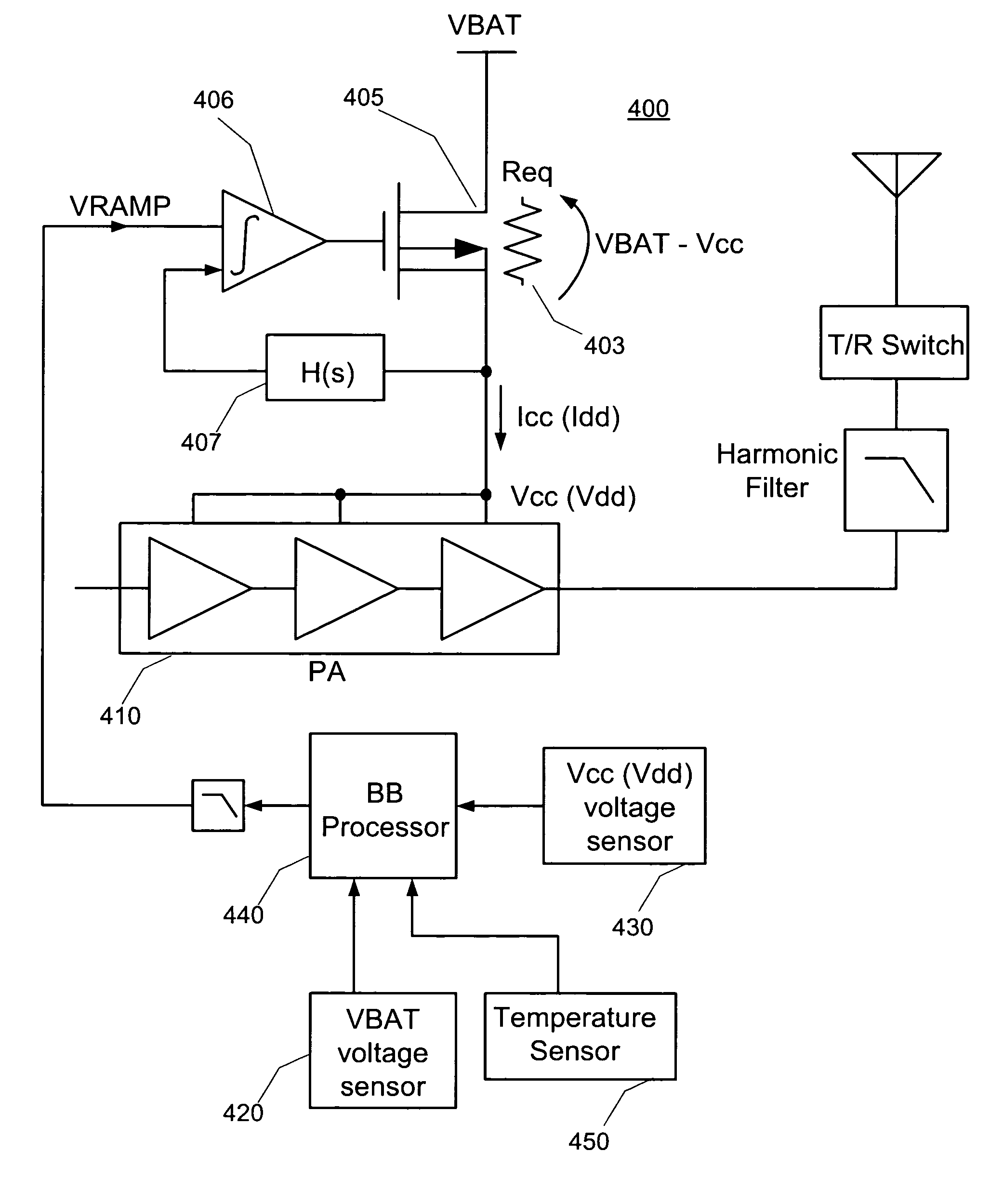
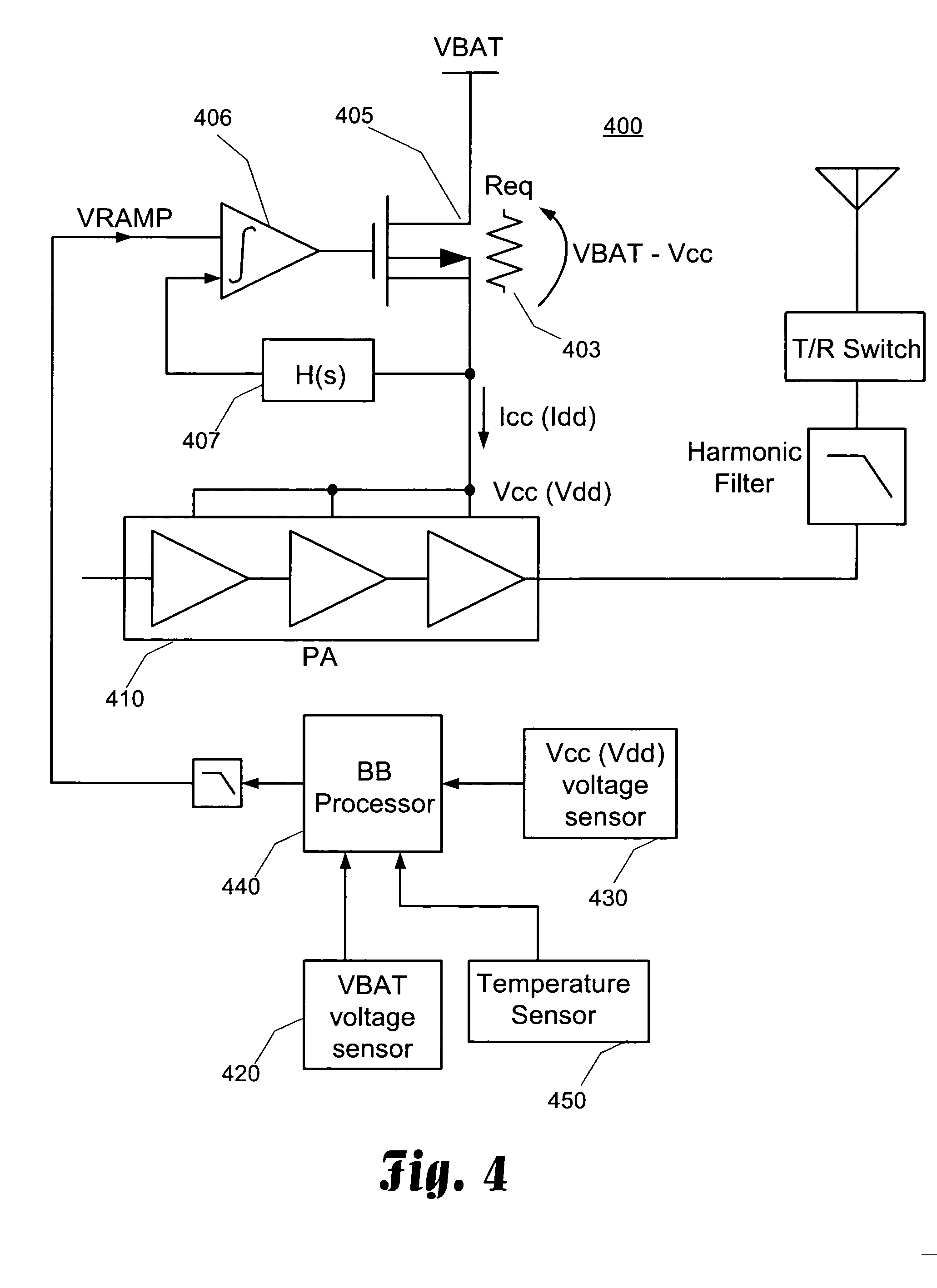
[0013] The present invention provides a solution to the deficiencies in the current art by providing a power control circuit that detects and limits the voltage and/or current being provided to a power amplifier. The present invention uses a pass transistor to control the voltage being provided to the power amplifier. In one embodiment of the present invention, the resistance characteristics of the pass transistor are determined. In operation, the voltage drop across the pass transistor is detected and divided by the expected resistance of the

Problems solved by technology

GMSK technology does not require an isolator which is a great benefit due to the size and cost of a typical isolator; however, the absence of such an isolator creates additional technological problems in a GSM system.
It is not uncommon for a mismatch condition of as high as 10:1 Voltage Standing Wave Ration (VSWR) or worse to be present at the antenna—which has a very significant affect on the output load impedance seen by the power amplifier.
Unfortunately, power amplifiers are typically designed to operate with a constant load impedance of 50 Ohms.
Thus, the efficiency of operation for a power amplifier is degraded as the VSWR increases and the load impedance changes.
Such a condition can be catastrophic in that it puts unnecessary drain onto the battery and thus reduces the time required between battery charge cycles.
In addition, as the efficiency of the power amplifier is decreased, the output spectrum can degrade and the spurious output level can exceed the levels required in the specifications for GSM technology.
Thus, there is a need in the art for a system that prevents loop saturation in a power amplifier system, which results in a decrease in the efficiency of a power amplifier operating in a GSM system.
Similarly, there is a need in the art to prevent such power amplifiers from drawing excessive amounts of current and degrading the output spectrum as a result of a decrease in efficiency.
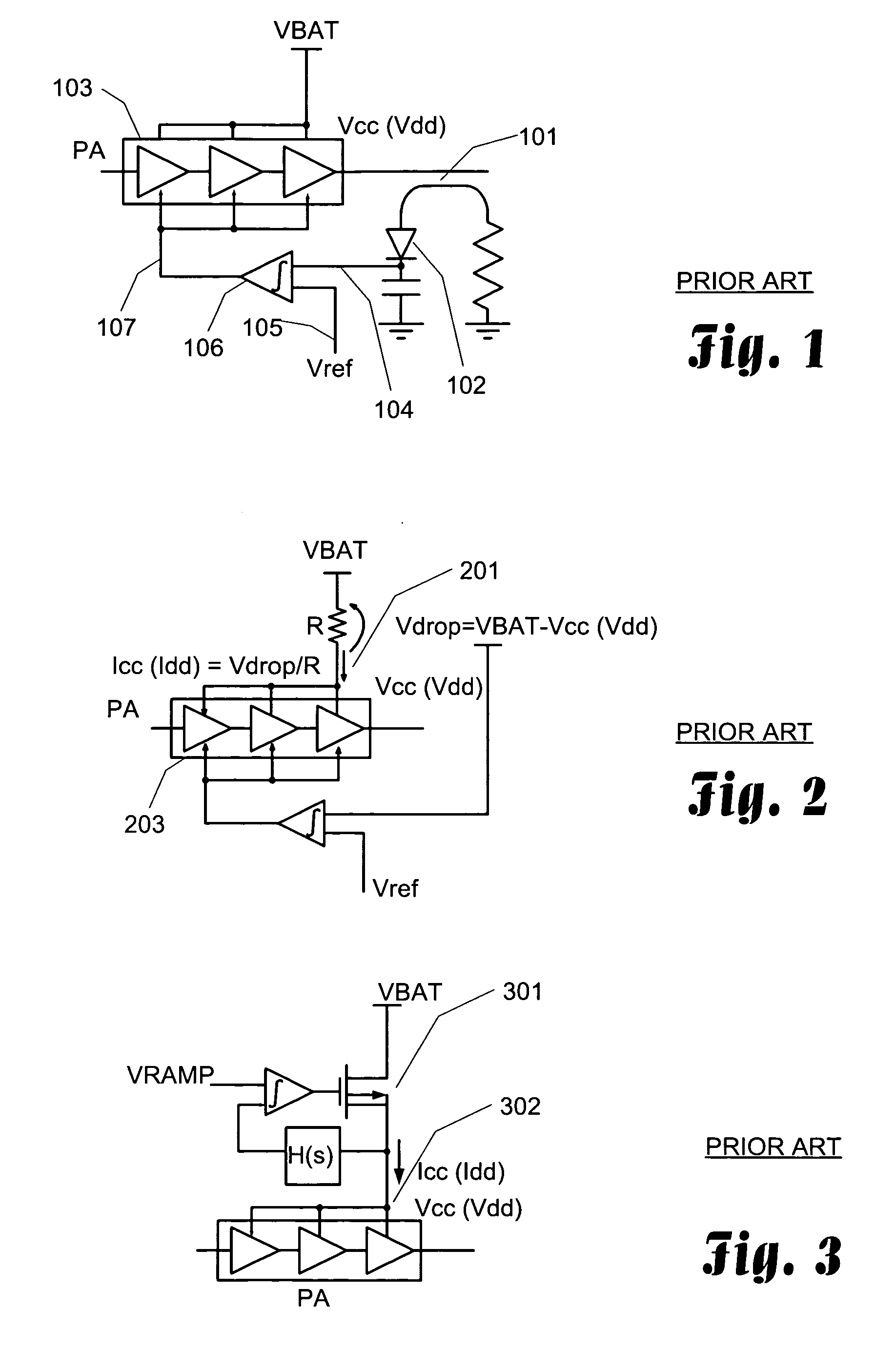
Three techniques have been introduced to the market to address this need in the art; however, as is shown in this document, these techniques fall short of being a viable solution. FIG. 1 is a circuit diagram illustrating the most conventional method for controlling the out power of a power amplifier.
This is also a closed loop system but does not offer the level of accuracy seen in the power detector system of FIG. 1.
This system is very effective at preventing the over current condition, but the output power variation control is not as accurate as the power detection method shown in FIG. 1.
Unfortunately, these ideal conditions are not guaranteed in handset applications.
Both the output power and current variations can be quite high when a mismatch load is presented.
The techniques illustrated in FIGS. 1-3 are insufficient in addressing the issues associated with GSM using GMSK modulation.
In GSM products, such an ideal condition is not available and the load impedance can greatly fluctuate.

Method used


Image

  • Method to control the supply power being provided to a power amplifier
  • Method to control the supply power being provided to a power amplifier
  • Method to control the supply power being provided to a power amplifier

Examples


Embodiment Construction

[0021] The present invention provides a power control circuit that operates to prevent, or reduce the likelihood of an over current condition in the power amplifier circuitry. In general, the present invention detects the power being utilized by a power amplifier by either monitoring the current supplied to the power amplifier or by monitoring the level of the supply voltage. Typically, when an over current condition exists in the power amplifier, the frequency characteristics of the power amplifier are either approaching, or are actually out of specification requirements. For instance, in a cellular transmission system, the mobile stations are required to limit the output power and spurious emissions according to specifications for the cellular transmission system. These specifications are established to prevent cross-talk and channel interference within the cellular frequency spectrum, as well as reduce electromagnetic interference.

[0022] Turning now to the figures in which like ...


PUM


Abstract

When a power amplifier operates near or in saturation, the quality of the output signal can be degraded and an over current condition can occur. To prevent this, the level of the power supply voltage being provided to the power amplifier must be monitored and controlled. One technique is to provide the supply power to the power amplifier through a pass transistor. By characterizing the resistance of the pass transistor and sensing the voltage drop across the pass transistor, the current being provided to the power amplifier can be determined. If this current is too high, the control input to the pass transistor can be adjusted to limit the current.

Description

CROSS-REFERENCE TO RELATED APPLICATIONS [0001] This application is related to U.S. patent application Ser. No. ______ entitled “METHOD TO PREVENT SATURATION IN POWER AMPLIFIER CONTROL LOOP” filed on the same date at this application and commonly assigned to the assignee of this application, which application is incorporated herein by reference in its entirety.TECHNICAL FIELD [0002] The present invention is directed towards radio frequency transmission technology and, more specifically, towards a technique to detect and prevent saturation in a power amplifier control loop of a transmitter and thereby, reduce spurious outputs caused by loop saturation and over current conditions. BACKGROUND [0003] Cellular telephone technology has greatly advanced since its inception in the early 80's. Today, the Global System for Mobile communication (GSM) is one of the more prominent technologies being deployed in cellular systems throughout the world. GSM is a digital cellular communications system...

Claims


Application Information

Patent Timeline
IPC IPC(8): H03F1/52H03F3/24H03G3/00H03G3/10H03G3/30
CPCH03F1/52H03F3/24H03G3/3047H03G3/007H03G3/004
Inventor YAMAZAKI, RYONOELLERT, WILLIAM
Owner PANASONIC CORP
Learn More