
Adaptive beam-forming system using hierarchical weight banks for antenna array in wireless communication system

a beam-forming system and hierarchical weight bank technology, applied in the field of wireless communication systems, can solve the problems of increasing the cost of producing such a system, increasing the cost of production, and requiring complex weight computing algorithms and powerful dsp processors, so as to simplify the transmission, reduce production costs, and simplify the system design

Inactive Publication Date: 2005-09-22
COMWARE
View PDF5 Cites 159 Cited by
  • Summary
  • Abstract
  • Description
  • Claims
  • Application Information

AI Technical Summary

Benefits of technology

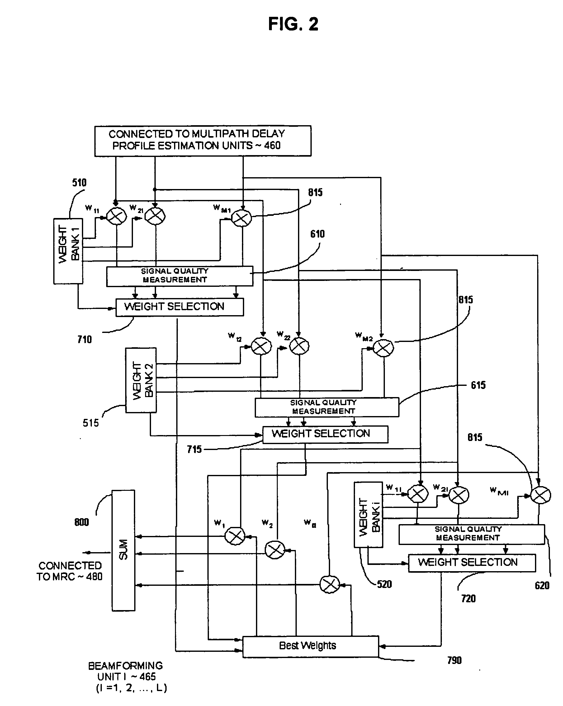
"The present invention provides an adaptive antenna array system for a wireless communication system that employs a beam-forming network to improve system performance. The beam-forming network uses pre-calculated weight banks to shift the beam pattern to point to the best beam look direction, based on the received signal quality metric such as instant power or SINR. The pre-calculated weight banks are computed a priori and do not require any absolute direction-of-arrival information. The invention reduces interference and background noise, improves signal-to-interference plus noise ratio, and is more flexible and adaptable to different wireless systems. The technical effects of the invention include improved beam-forming performance in angle spread and multipath propagation environments, reduced analog hardware costs, and improved signal quality."

Problems solved by technology

The cost of producing such a system is proportional the number of look directions that must be supported and can become expensive due to the need for one set of analog hardware for each beam look direction.
Finally, the beam-forming technologies associated with adaptive antenna array systems, require complex weight computing algorithms and powerful DSP processors, which are expensive and consume a great deal of battery power.
Further, with regard to U.S. Pat. No. 6,049,307, because the amplitude and phase adjusting procedure is carried out on the RF stage with phase shifter and the RF power combiner / feeder / divider are analog components, the application of this technique would be limited cost and size in the wireless communication systems.
Also, this technique can not be applied in the multipath propagation environment as the multipath components can not be separated by this technique.

Method used


Image

  • Adaptive beam-forming system using hierarchical weight banks for antenna array in wireless communication system
  • Adaptive beam-forming system using hierarchical weight banks for antenna array in wireless communication system
  • Adaptive beam-forming system using hierarchical weight banks for antenna array in wireless communication system

Examples


Embodiment Construction

[0049] The present invention provides a wireless communication system employing an adaptive beam-forming network that utilizes hierarchical weight banks. It will be appreciated that such a system may be employed at either a base station or mobile terminal, or both.

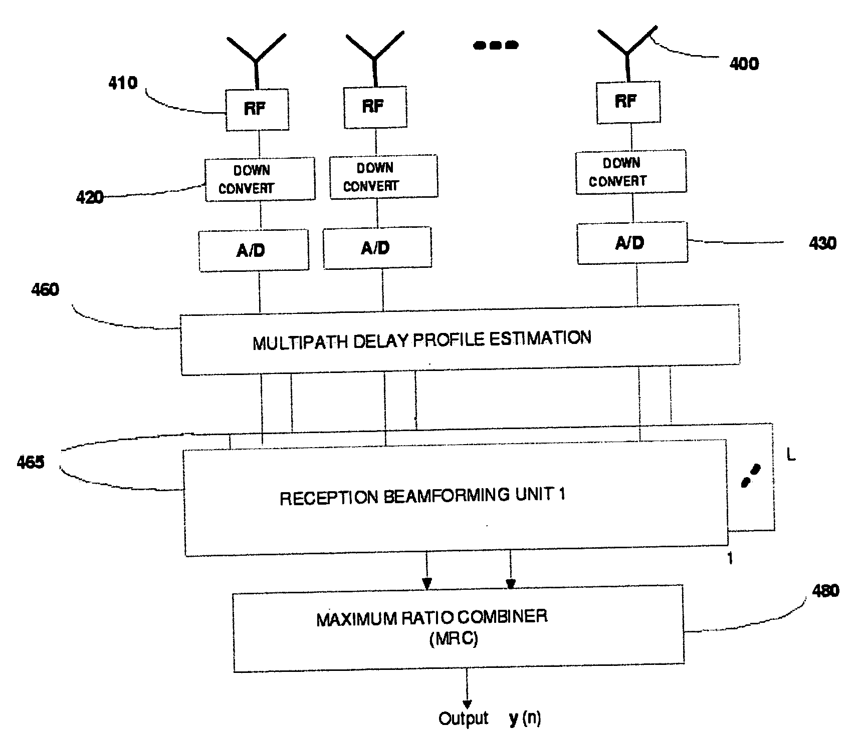
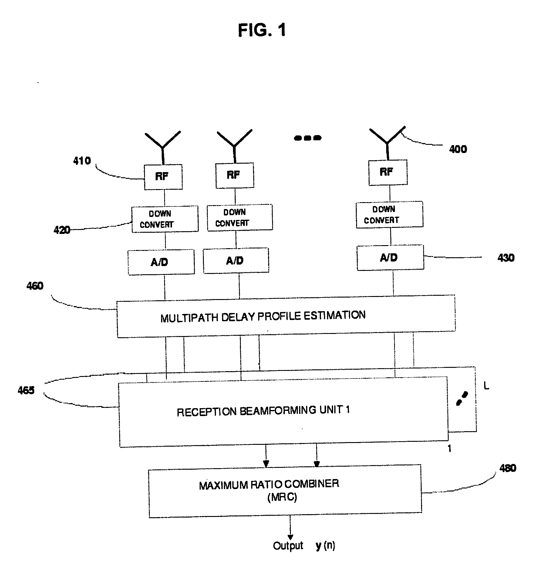
[0050]FIG. 1 schematically depicts a receiver beam-forming system, in accordance with an embodiment of the present invention. The system comprises an antenna array with M antenna elements 400. These antenna elements may be configured as omni-directional, sectorized, or a combination of omni-directional and sectorized elements.

[0051] The antenna array feeds into a plurality of RF units 410 and down converters 420, and then converted into digital signals by A / D units 430. The M output digital signals from A / D converters are fed into a multipath delay profile estimation unit 460.

[0052] To enhance performance in a multipath propagation environment, the multipath delay profile estimation unit 460 is used to distinguish the m...


PUM


Abstract

An adaptive beam-forming system using hierarchical weight banks for antenna arrays in wireless communication systems is disclosed. The present invention can be applied for both reception and transmission beam-forming. The hierarchical weight banks contain weights that are pre-calculated based on pre-set beam look directions. By comparing measurements of chosen signal quality metrics for pre-set look directions, the best weights, and thus the best beam look direction, can be selected from the weight banks.

Description

BACKGROUND OF THE INVENTION [0001] 1. Field of the Invention [0002] The present invention relates wireless communications systems and, more particularly, to beam-forming technologies and associated methodologies. [0003] 2. Description of the Related Art [0004] Antenna array systems with desired beam-patterns have been considered as a solution to improve the spectral efficiency and communication quality for both uplink (mobile-to-base station) and downlink segments (base station-to-mobile) in wireless communication systems. The beam-forming technologies employed with antenna arrays can be a powerful means to increase system capacity, improve quality of service (QoS), reduce co-channel interference (CCI), and multipath fading. Generally, this is because a transmitter / receiver using an antenna array can increase or decrease antenna gain in the intended look directions (i.e., approximate direction of mobile terminal location). [0005] There are several ways to realize such beam-forming t...

Claims


Application Information

Patent Timeline
Patent Type & Authority Applications(United States)
IPC IPC(8): H01Q3/22H01Q3/26H04B7/06H04B7/08
CPCH01Q3/2682H01Q3/2605
Inventor MAO, JIANSOMERLOCK, OSCAR FREDERICK III
Owner COMWARE
Learn More