Module for amplifying signal light with remote excitation-light and optical-fiber communication system including the same

a technology of excitation light and module, which is applied in the direction of electromagnetic repeaters, instruments, optical elements, etc., can solve the problems of affecting fabrication and running costs, affecting the arrangement of relays, and so much cost, so as to achieve the effect of gradually enhancing the performance of the module and the optical fiber communication system

Active Publication Date: 2005-09-22
NEC CORP
View PDF3 Cites 8 Cited by
  • Summary
  • Abstract
  • Description
  • Claims
  • Application Information

AI Technical Summary

Benefits of technology

[0055] The module and the optical-fiber communication system both in accordance with the present invention are applicable to various uses, and hence, provides advantages that accuracy with which how an optical transmission line to which the amplification of a signal light with a remote excita

Problems solved by technology

Reduction in an optical SNR causes an error in received codes.
The number of relays and stations in which relays are arranged much influences fabrication and running costs.
Thus, the amplification of a signal light with a remote excitation-light is frequently applied to a field where it is difficult to supply power to an optical relay amplifier, or it would cost so much to do so.
However, the amplification of a signal light with a remote excitation-light is accompanied with problems.
A part of the problems is caused that introduction of the amplification of a signal light with a remote excitation-light, that is, introduction of a module for amplifying a signal light with a remote excitation-light, into an optical transmission system will lose “transparency” of an optical transmission-line fiber.
The first problem is that the present amplification of a signal light with a remote excitation-light has orientation, in other words, the present amplification of a signal light with a remote excitation-light will lose “transparency” relating to orientation.
Specifically, if the present amplification of a signal light with a remote excitation-light is introduced into an optical transmission system, it would be difficult for the optical transmission system to operate in an opposite direction.
The above-mentioned first problem exerts a harmful influence on a case in which the number of up-link and down-link transmission lines and a ratio

Method used


Image

  • Module for amplifying signal light with remote excitation-light and optical-fiber communication system including the same
  • Module for amplifying signal light with remote excitation-light and optical-fiber communication system including the same
  • Module for amplifying signal light with remote excitation-light and optical-fiber communication system including the same

Examples


first embodiment

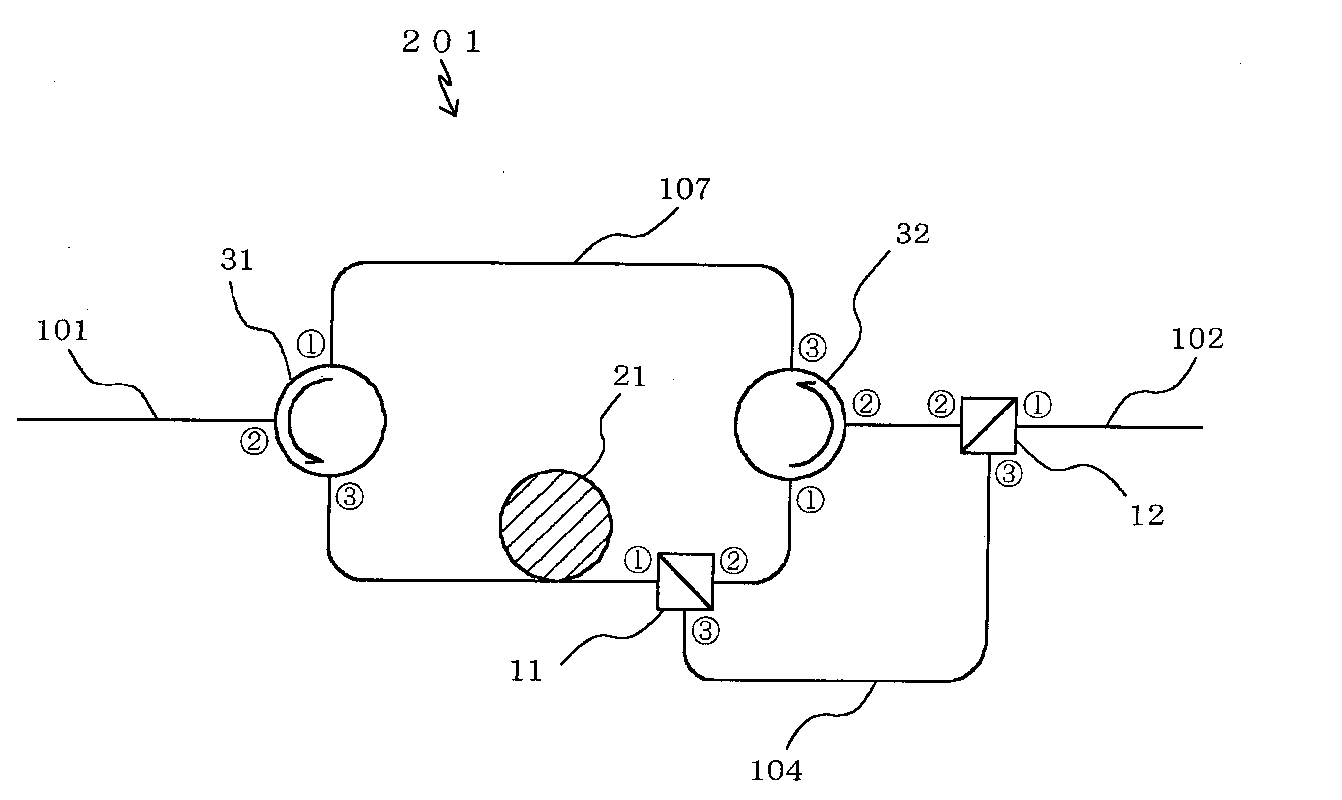
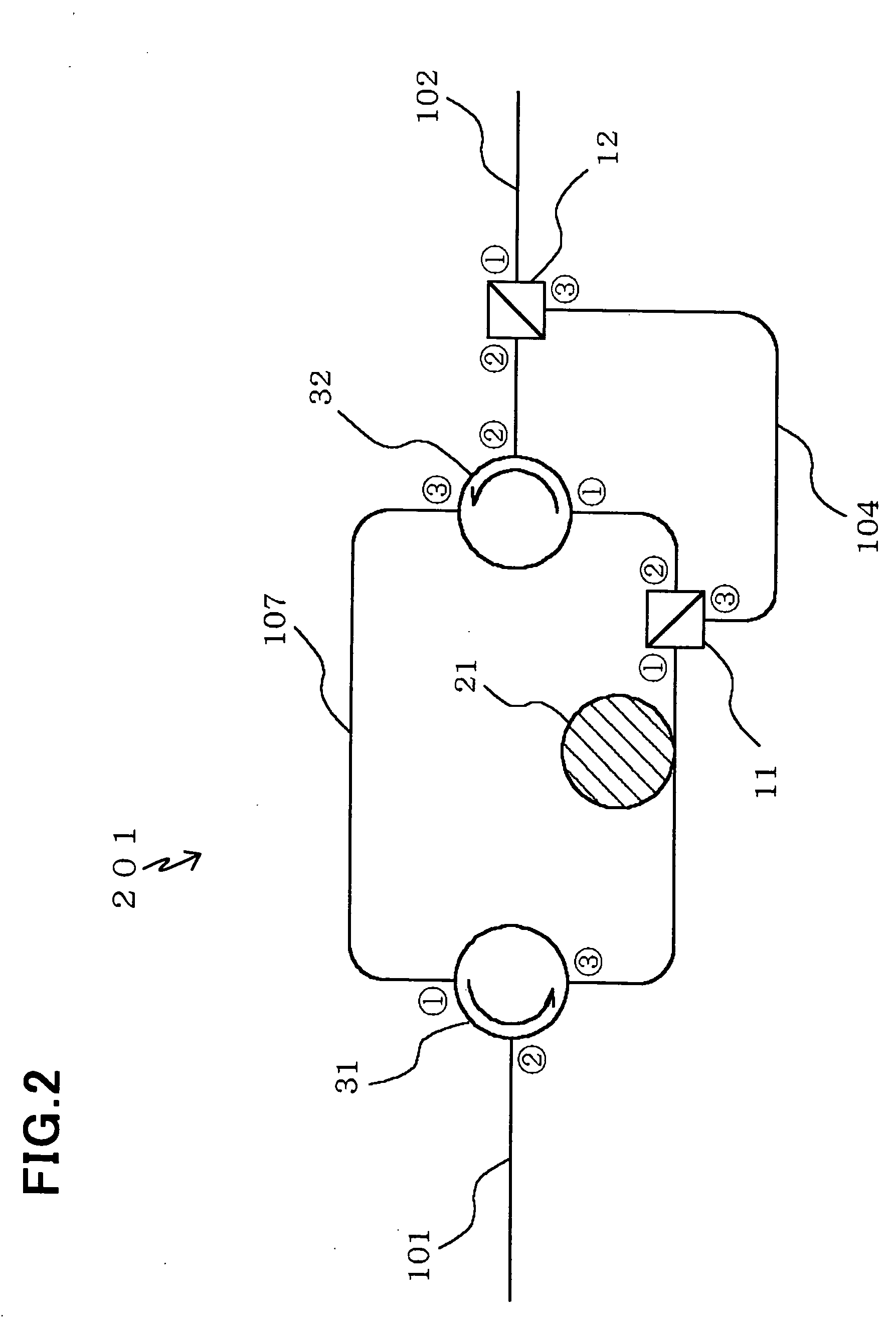
[0076]FIG. 2 is a block diagram of a module 201 for amplifying a signal light with a remote excitation-light, in accordance with the first embodiment of the present invention.

[0077] The module 201 is comprised of a first optical input / output line 101 through which a signal light is transmitted, a second optical input / output line 102 through which a signal light is transmitted, an optical amplifier 21 which amplifies a signal light on receipt of an excitation light transmitted from an excitation-light source (not illustrated) through the second optical input / output line 102, a first bypass circuit 107 optically connected to later mentioned first and second optical connectors 31 and 32 to allow a signal light to bypass the optical amplifier 21, a first optical connector 31 which optically connects the first optical input / output line 101 to the optical amplifier 21, and further optically connects the first optical input / output line 101 to the first bypass circuit 107, a second optical...

second embodiment

[0087]FIG. 3 is a block diagram of a module 202 for amplifying a signal light with a remote excitation-light, in accordance with the second embodiment of the present invention.

[0088] The module 202 is structurally different from the module 201 illustrated in FIG. 2 in that the module 202 includes third and fourth filters 61 and 62 in place of the first and second optical 3-port circulators 31 and 32, and that the module 202 further includes first and second isolators 63 and 64.

[0089] The first isolator 63 is located between the third filter 61 and the optical amplifier 21, and the second isolator 64 is located between the first filter 11 and the fourth filter 62.

[0090] The third filter 61 has first, second and third ports. The second port {circle over (2)} is a port through which a signal light comprised of a signal light having a first wavelength band and a signal light having a second wavelength band, combined to each other, is input and output, the first port {circle over (1)}...

third embodiment

[0097] A module having a function symmetrical with the function of the module 202 illustrated in FIG. 3 may be more effectively used than the module 202. In such a module, a light having a first wavelength band is transmitted in a fixed direction, whereas a light having a second wavelength band is transmitted in opposite directions. Such a module is explained hereinbelow as a module 203 in accordance with the third embodiment.

[0098]FIG. 4 is a block diagram of a module 203 for amplifying a signal light with a remote excitation-light, in accordance with the third embodiment of the present invention.

[0099] The module 203 is structurally different from the module 202 illustrated in FIG. 3 in port-arrangement in the third and fourth filters 61 and 62.

[0100] The third filter 61 has first, second and third ports. The second port {circle over (2)} is a port through which a signal light comprised of a signal light having a first wavelength band and a signal light having a second waveleng...


PUM


Abstract

A module for amplifying a signal light with a remote excitation-light, includes (a) a first optical input/output line through which a signal light is transmitted, (b) a second optical input/output line through which a signal light is transmitted, (c) an optical amplifier which amplifies a signal light on receipt of an excitation light transmitted through the first or second optical input/output line, (d) a bypass circuit which allows the signal light to bypass the optical amplifier, (e) a first optical connector which optically connects the first optical input/output line to the optical amplifier, and further optically connects the first optical input/output line to the bypass circuit, and (f) a second optical connector which optically connects the second optical input/output line to the optical amplifier, and further optically connects the second optical input/output line to the bypass circuit.

Description

BACKGROUND OF THE INVENTION [0001] 1. Field of the Invention [0002] The invention relates to a module for amplifying a signal light with a remote excitation-light, and further to an optical-fiber communication system including the same. [0003] 2. Description of the Related Art [0004] A transmission line in an optical long-range transmission system for transmitting an optical signal by hundreds of kilometers or longer is comprised usually of an optical transmission-line fiber, and an optical relay amplifier for compensating for attenuation of a signal light in the optical transmission-line fiber. A signal light is amplified in the optical amplifier, but receives a noise light while being amplified, resulting in reduction in an optical signal-noise ratio (SNR). Reduction in an optical SNR causes an error in received codes. [0005] Reduction in an optical SNR is dependent on both an intensity with which a signal light is input into an optical amplifier, and how a signal light is amplifi...

Claims


Application Information

Patent Timeline
IPC IPC(8): G02B6/28H01S3/10H01S3/00H01S3/06H01S3/067H01S3/23H04B10/29H04B10/297
CPCH01S3/005H01S3/0064H01S3/06725H04B10/2916H01S3/06787H01S3/2383H01S3/06754
Inventor ITO, TOSHIHARU
Owner NEC CORP
Why Eureka
Try Eureka