Light barrier

Inactive Publication Date: 2005-09-22
SICK AG
View PDF11 Cites 9 Cited by
  • Summary
  • Abstract
  • Description
  • Claims
  • Application Information

AI Technical Summary

Benefits of technology

[0010] Another important advantage of the invention is that the cross braces function as a light tube between the optoelectronic elements and the optical function elements. This eliminates a considerable number of structural parts that would otherwise be needed. Housings constructed in accordance with the present invention have not only a mechanical function, but also an optical one because the cross braces prevent the optoelectronic transmitting elements from emitting light sideways at the transmitting unit and prevent scattered light from reaching the receiving elements at the receiving unit.
[0011] For this, the cross braces are preferably configured as substantially continuous, closed cross walls.
[0012] It is especially advantageous if two intersecting cross braces are arranged between adjacent transmitting or receiving units. The intersecting cross braces provide the housing with a high degree of rigidity. Furthermore, the intersecting cross braces form a simple honeycomb structure which fulfills the function o

Problems solved by technology

The cross braces result in a high flexur

Method used


Image

  • Light barrier
  • Light barrier
  • Light barrier

Examples


Example

[0020] The housings at the transmitting end and the receiving end of the light grid are the same. The only difference is that different optoelectronic elements and the optical function elements are used at the transmitting end and the receiving end to perform their different functions.

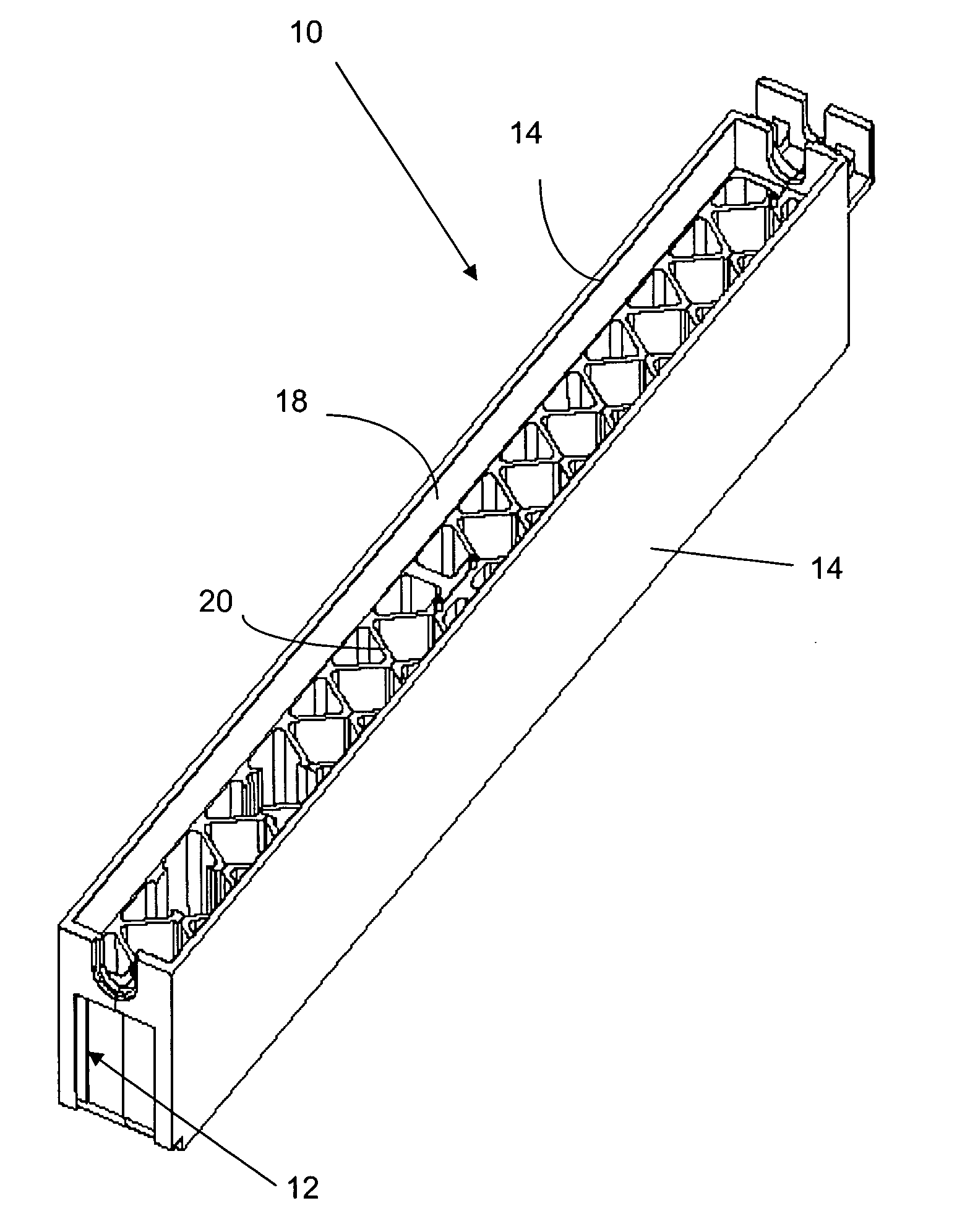
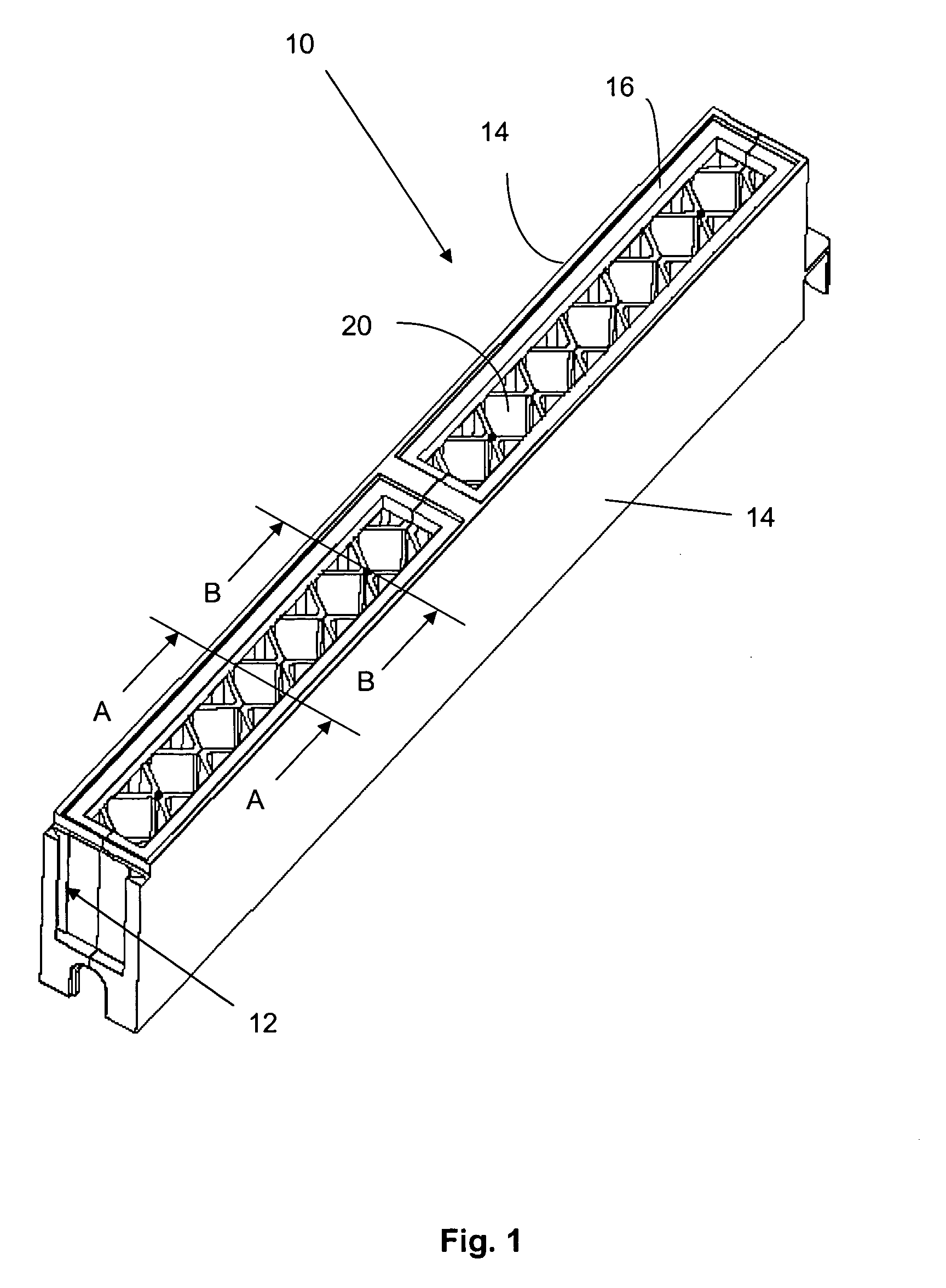
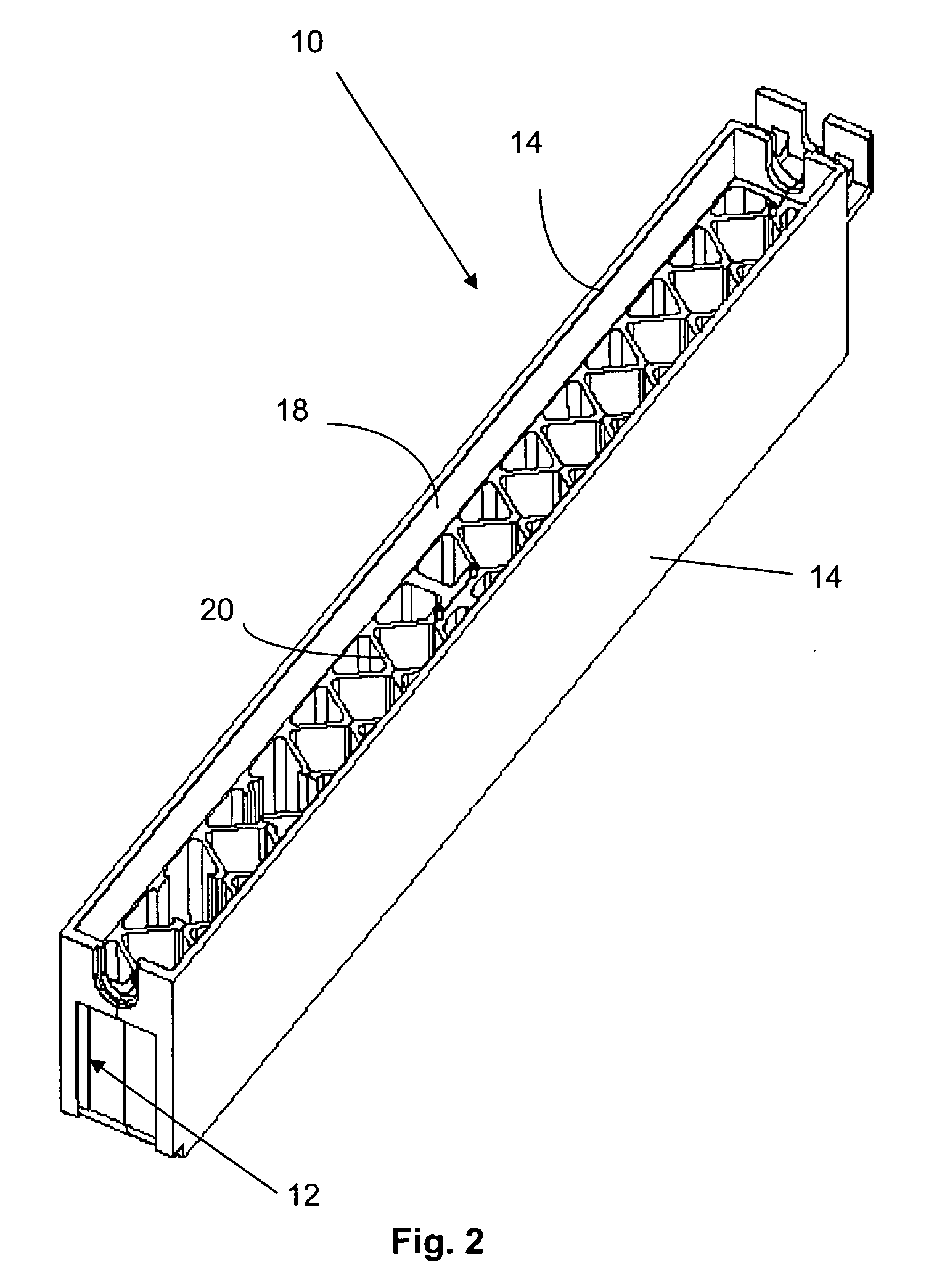
[0021] Housing 10 is a one-piece plastic part, which is preferably injection molded. The housing has the shape of an elongated strip or bar which has brackets, for example, for mounting the housing to a place of installation.

[0022] Housing 10 has two closed side walls 14 that are continuous in the longitudinal direction of the housing. The height of the side walls 14 corresponds to the overall structural height of the housing. The housing 10 is closed at its end faces, as is shown in FIGS. 1 and 2. The housing can be provided with a dovetail connection 12 at one end surface, as is shown in FIGS. 1 and 2. Two or more housings can be joined axially flush when the light grid requires a greater length. I...


PUM


Abstract

A strip-like housing of a light grid has two side walls that extend over its entire housing length and that are joined together by cross braces. The cross braces form a honeycomb structure, in which the transmitting and receiving elements of the light grid are installed.

Description

BACKGROUND OF THE INVENTION [0001] The invention concerns a light barrier or grid with transmitting and receiving units longitudinally arranged at intervals in a strip-like housing, each of them including an optoelectronic element that is spaced apart from at least one optical function element. [0002] Light grids are extensively used for the recognition and monitoring of objects on conveyor belts, for baggage inspection on conveyor belts, for controlling elevator doors, for protecting body parts at machine tools, for access control of people and vehicles, etc. The light grids have spaced-apart transmitting units arranged in a strip-like housing and receiving units arranged in a strip-like housing with a corresponding spacing. The transmitting units emit light beams, typically infrared light, which impinge on the receiving units. Interruptions of the light beams are detected and evaluated. [0003] The transmitting units and the receiving units each include an optoelectronic element an...

Claims


Application Information

Patent Timeline
IPC IPC(8): G01V8/20
CPCG01V8/20
Inventor BOECKEL, GUENTERFRIEDRICH, RALFMEYER, CHRISTOFWUESTEFELD, MARTIN
Owner SICK AG
Why Eureka
Try Eureka