Fuser and temperature control method

a temperature control and temperature control technology, applied in the field of fixing apparatus, can solve the problems of shortening the life of the heating roller, reducing the sensitivity of the detecting element, and degrading the surfa

Active Publication Date: 2005-09-22
KK TOSHIBA +1
View PDF34 Cites 31 Cited by
  • Summary
  • Abstract
  • Description
  • Claims
  • Application Information

AI Technical Summary

Problems solved by technology

However, the contact-type temperature detecting element slides on the surface of the heating roller, so that it may degrading the surface, shortening the life of the heating roller.
When the surface is degraded, the sensitivity of the detecting element decreases, with the result that wrong temperature may be detected.
Hence, it has been difficult to accurately detect the temperature of a heating roller.
However, since the radiation-detecting device is installed in a fixing apparatus where toner and paper dust are scattered, wrong detection may occur due to smudges.
To solve this, it is effective to provide not only cleaning means to the temperature detecting element but also cleaning means to the radiation detecting unit; however they increase cost.
In this way, in the case where a non-contact temperature-detecting element is used, when infrared ray radiation rate changes, the temperature of the heating roller cannot be sensed accurately.
Since heating means for heating the heating roller control heat generation depending upon the surface temperature of the heating roller inaccurately detected, the heating roller is not controlled at a proper temperature.

Method used


Image

  • Fuser and temperature control method
  • Fuser and temperature control method
  • Fuser and temperature control method

Examples


first embodiment

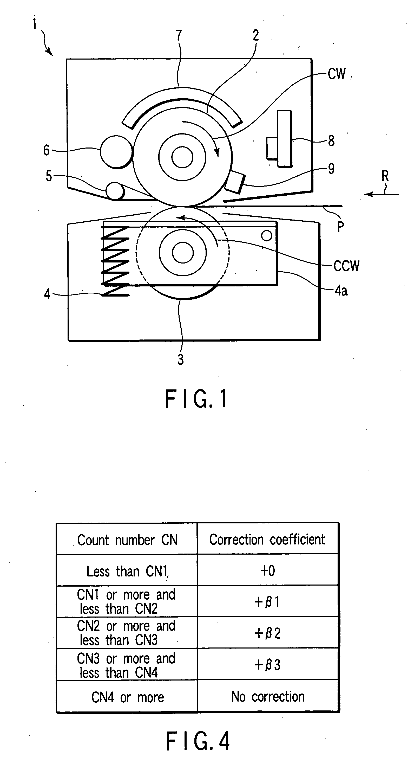
[0040]FIG. 1 shows a fixing apparatus to which an embodiment of the present invention can be applied.

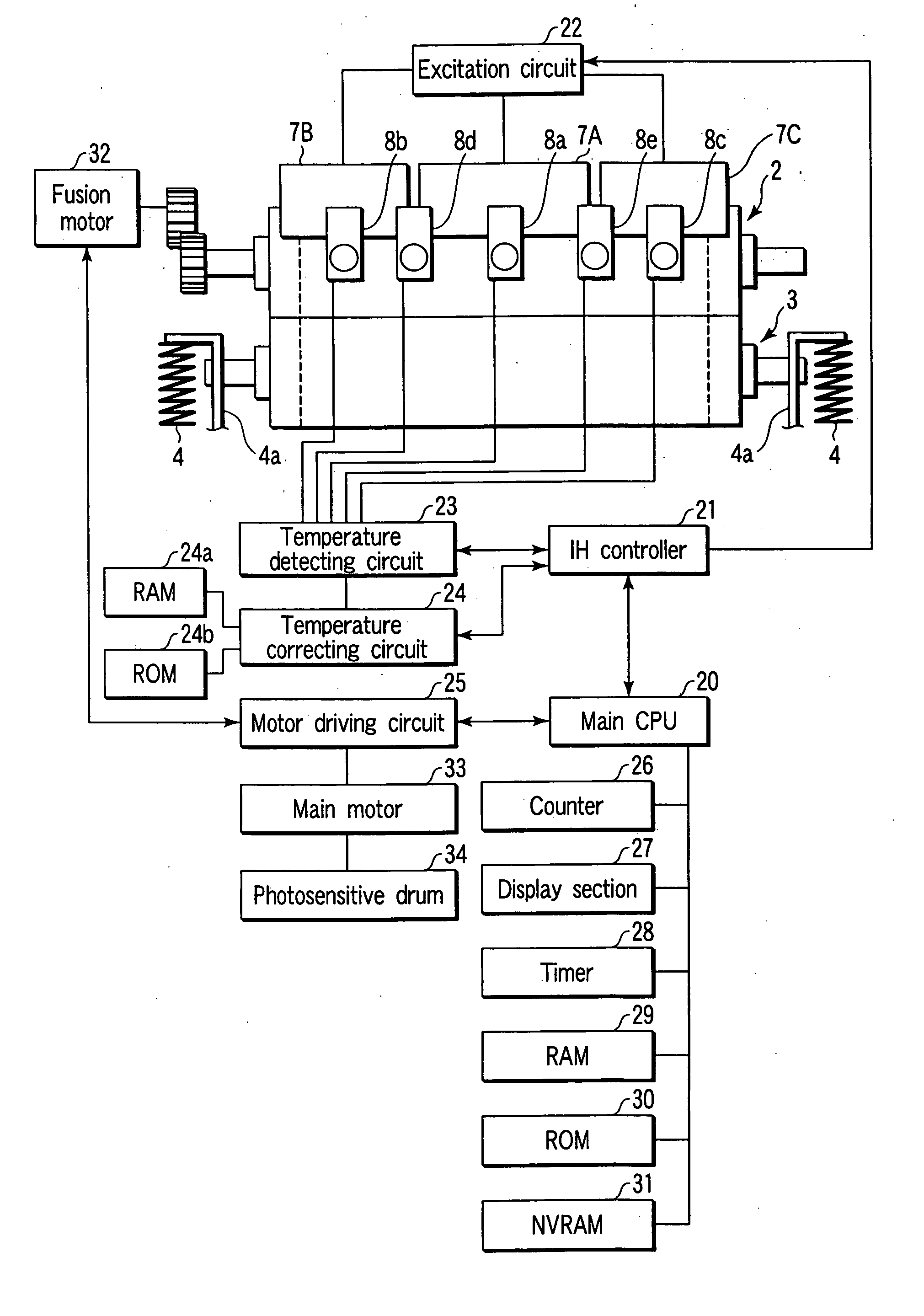
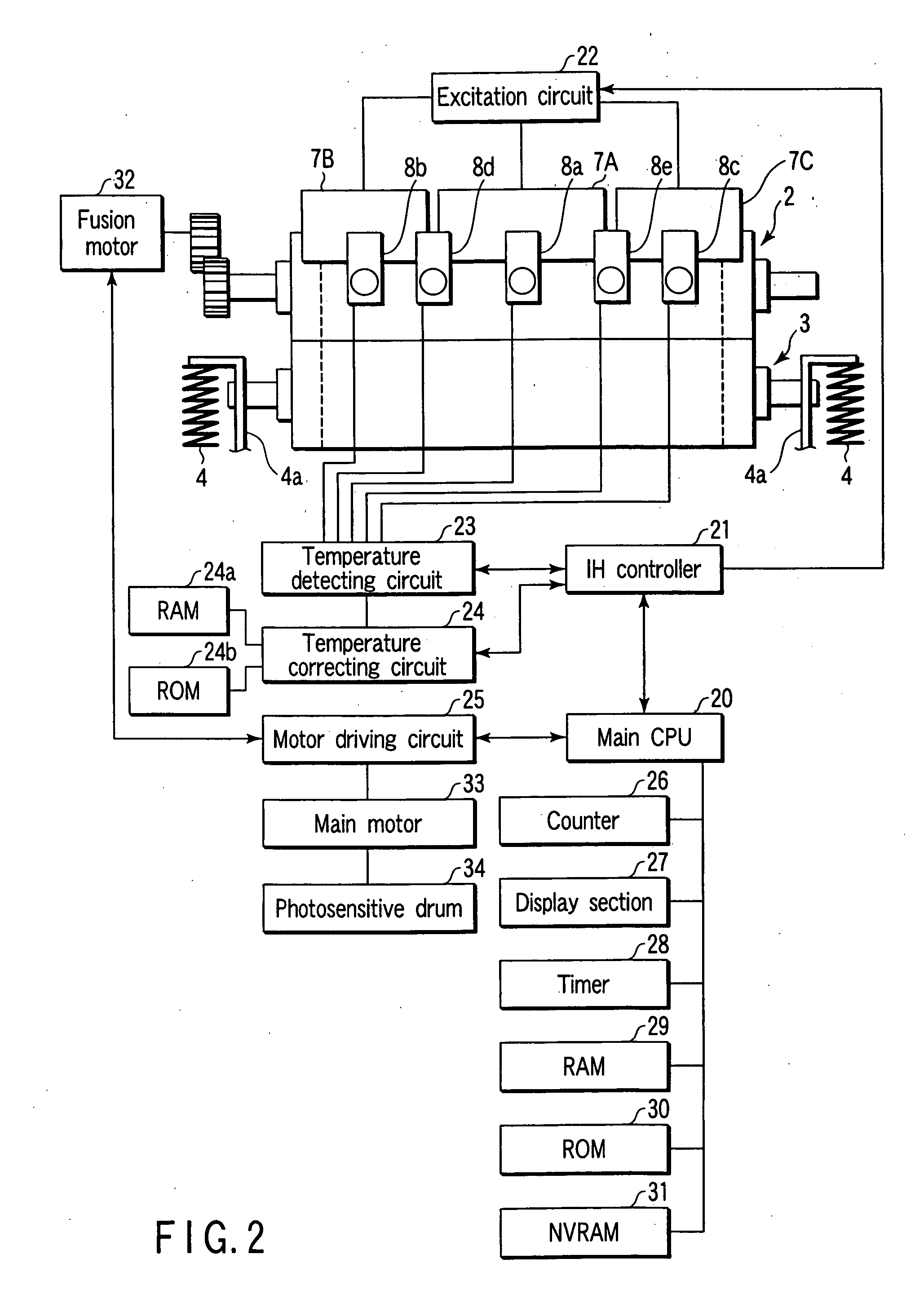
[0041] As shown in FIG. 1, a fixing apparatus 1 has a heating roller 2, pressurizing roller 3, pressurizing spring 4, separation nail 5, cleaning roller 6, heat-induction unit 7, temperature detecting mechanism 8 and thermostat 9.

[0042] The heating roller 2 has a surface formed of an conductive member composed of iron, stainless steel, nickel, or an alloy of aluminium and stainless steel.

[0043] The pressurizing roller 3 is an elastic roller formed of a rotation axis having a predetermined diameter covered with a silicon rubber or fluorine rubber of a predetermined thickness.

[0044] The pressurizing spring 4 applies a predetermined pressure to the axis of the heating roller 2 such that the pressuring roller 3 is maintained in posture almost in parallel to the axis of the heating roller 2. On the other hand, the pressurizing spring 4 can be maintained in parallel to the heating roll...

second embodiment

[0104] Next, referring to FIGS. 10 and 11, the second embodiment will be explained. With respect to the structural elements shown in FIGS. 10 and 11, like reference numerals are used to designate like structural elements corresponding to those like in the first embodiment and any further explanation is omitted for brevity's sake.

[0105]FIG. 10 shows an example of a fixing apparatus to which a second embodiment is applied.

[0106] As shown in FIG. 10, a fixing apparatus 101 has a temperature detecting mechanism 40. The temperature detecting mechanism 40 is provided in no contact with the surface of the heating roller 2 and has an infrared-ray sensing unit 41 which converts infrared radiation energy from the heating roller 2 to electric power and a temperature signal circuit board 42 which converts the electric power from the infrared-ray sensing unit 41 into an electric signal.

[0107] The infrared sensing unit 41 is provided in the close proximity of the surface of the heating roller ...


PUM


Abstract

According to one aspect of the present invention, there is provided a fixing apparatus having a non-contact temperature detecting unit which detects temperature by sensing infrared rays emitted from the a heating roller and a difference between real temperature and the temperature detected by the non-contact temperature detecting unit, produced by time-lag until reaching the infrared rays emitted from the heating roller is corrected.

Description

BACKGROUND OF THE INVENTION [0001] 1. Field of the Invention [0002] The present invention relates to a fixing apparatus installed in image forming apparatuses, copiers, and printers where an image is formed on a transfer material by an electrophotographic process, for fusing and fixing a development agent placed on the transfer material to it. [0003] 2. Description of the Related Art [0004] In copiers and printers using an electron process, it is known that a toner image formed on a photoconductive drum is transferred onto a transfer material and thereafter the toner image is fused in a fixing apparatus having a heating roller and a pressurizing roller and fixed onto the transfer material. [0005] At this time, for controlling the temperature of the heating roller, a method of detecting the surface temperature of the heating roller by a detecting element, which is arranged in contact with the surface of the heating roller, has been known. However, the contact-type temperature detecti...

Claims


Application Information

Patent Timeline
IPC IPC(8): G03G15/20G03G21/00
CPCG03G15/2042
Inventor SONE, TOSHIHIROTAKAGI, OSAMUKINOUCHI, SATOSHITSUEDA, YOSHINORI
Owner KK TOSHIBA
Why Eureka
Try Eureka