Oscillating water column wave energy converter incorporated into caisson breakwater

a technology of oscillating water column and wave energy converter, which is applied in the direction of caissons, water-power plants, buttress dams, etc., can solve the problems of inability to protect a port, inability to amplify waves, and dangers of overtopping discharg

Inactive Publication Date: 2005-09-22
BOCCOTTI PAOLO
View PDF2 Cites 30 Cited by
  • Summary
  • Abstract
  • Description
  • Claims
  • Application Information

AI Technical Summary

Benefits of technology

[0024] (iii) the width and height of the room 3 is increased,

Problems solved by technology

Of course, the wave amplification may be dangerous for boats and ships approaching a port, and the overtopping discharge may be dangerous for persons, facilities, and boats inside a port.
These breakwaters are able to protect beaches from erosion, but they cannot protect a port because a part of the wave energy goes beyond these breakwaters.
As a wave energy converter the caisson of U.S. Pat. No. 6,450,732 B1 has the turbine beneath the sea level, which implies some difficulty of maintenance and the need for a water-tight room for a generator.
Moreover, to improve the efficiency, OWCs need some complex devices for phase control.

Method used


Image

  • Oscillating water column wave energy converter incorporated into caisson breakwater
  • Oscillating water column wave energy converter incorporated into caisson breakwater
  • Oscillating water column wave energy converter incorporated into caisson breakwater

Examples


Embodiment Construction

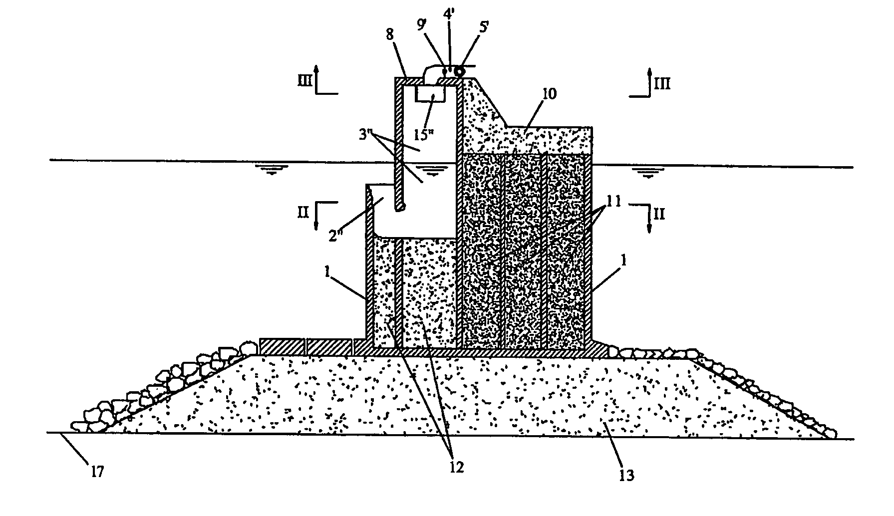
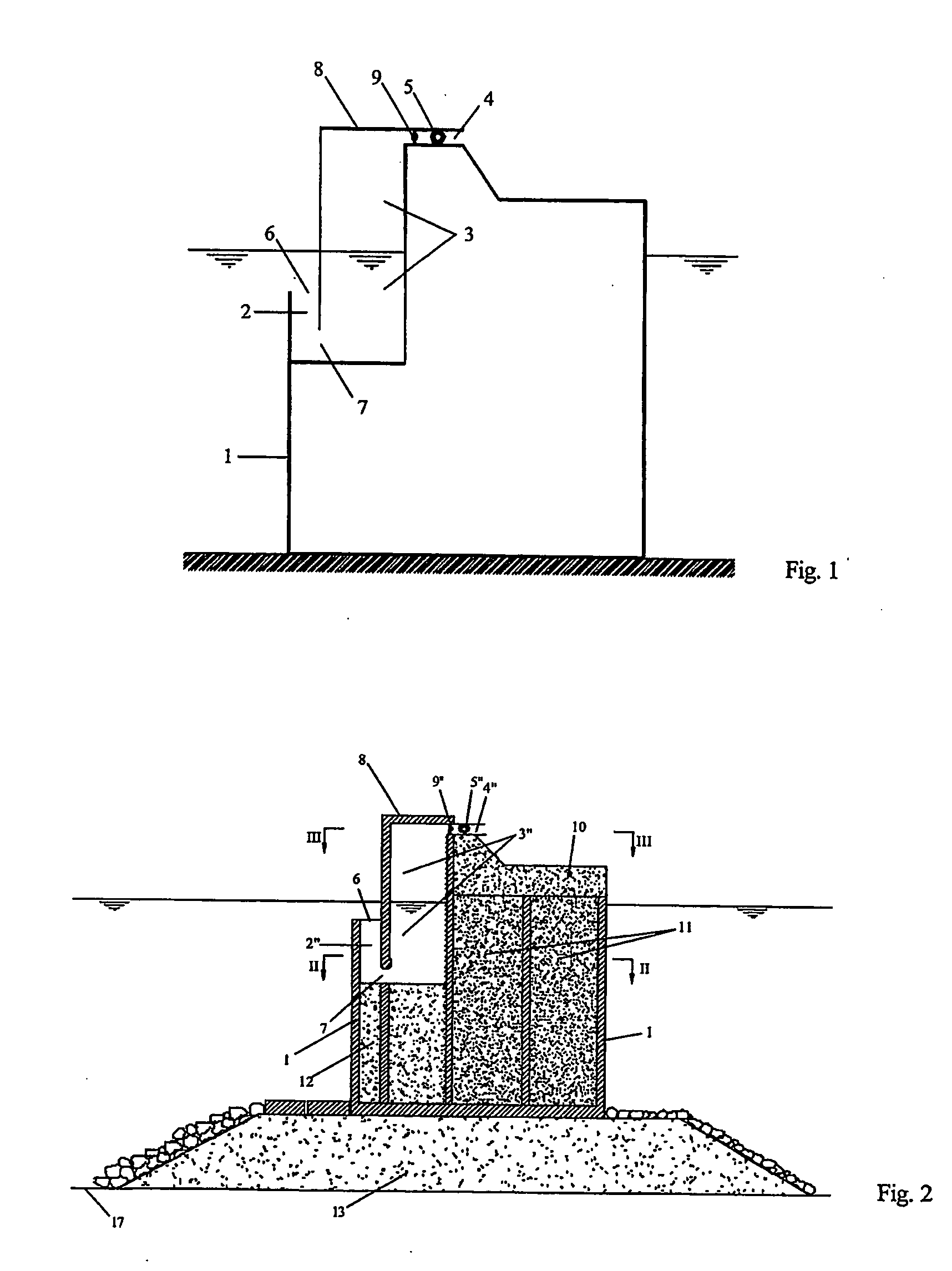
[0043] The breakwater of the present invention consists of caissons close to each other or joined together, like a conventional caisson breakwater. Like casssons of a conventional caisson breakwater, the caissons of the breakwater of the present invention (see FIGS. 2 to 12) typically rest on a rubble mound foundation 13 on the seabed 17, and a caisson 1 of the breakwater consists of cells which are filled with sand and / or gravel 11 and / or concrete 12. Like in a conventional caisson breakwater, a superstructure 10 is cast in concrete above each caisson.

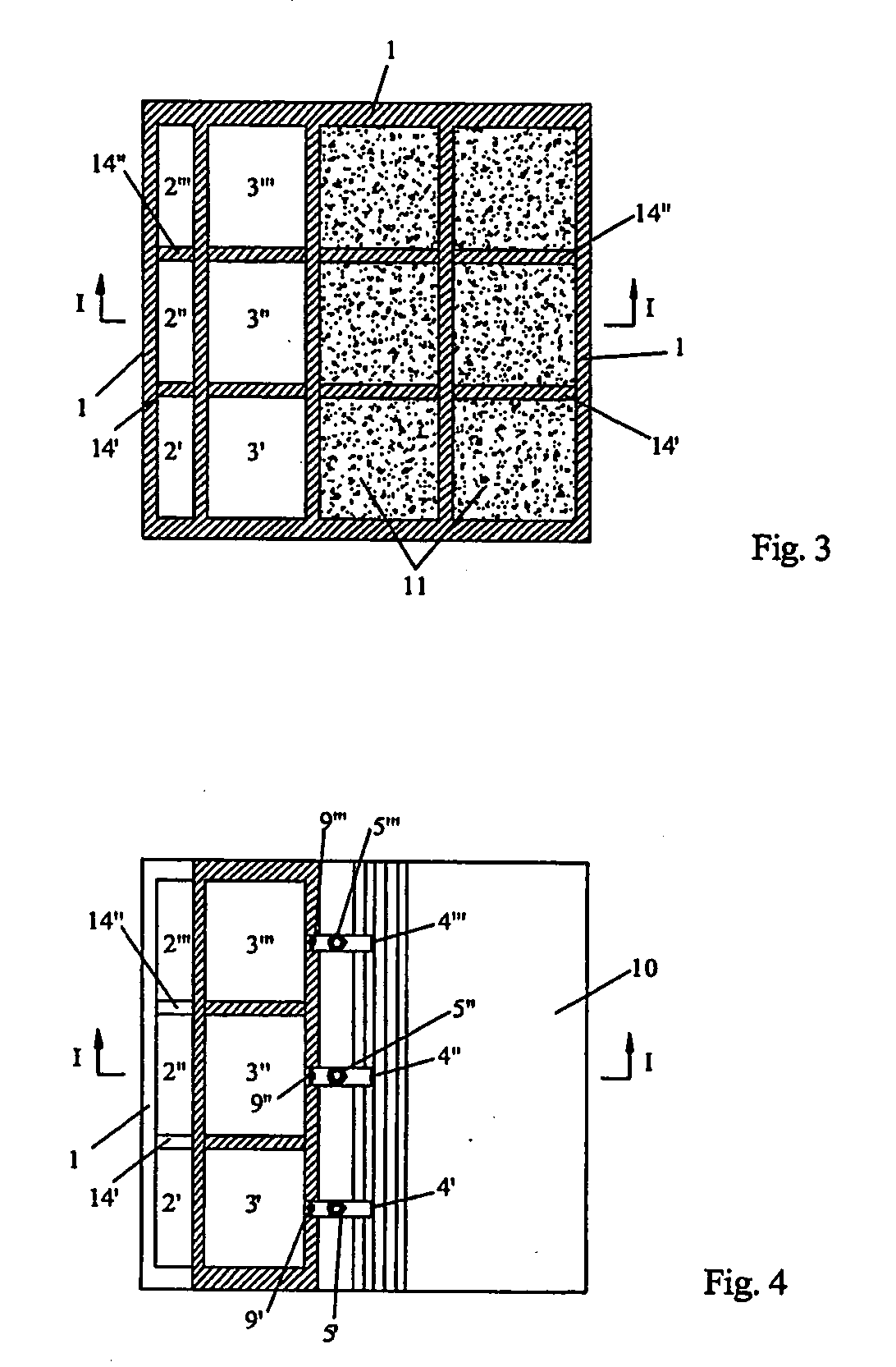
[0044] In a first embodiment (FIGS. 2-3-4), some vertical stiffening-walls 14′,14″ subdivide the vertical duct into sections 2′,2″,2′″, and subdivide the room 3 into cells 3′,3″,3′″. Each of said cells 3′,3″,3′″ is connected with the atmosphere by its own air-duct 4′,4″,4′″ with self-rectifying turbines (e.g. Wells turbines) 5′,5″,5′″ and valves 9′,9″,9′″.

[0045] In a second embodiment (FIGS. 5-6-7), the vertical walls 14′,14″,14IV,1...


PUM


Abstract

A caisson breakwater provided with vertical duct 2″, room 3″, air-duct 4″, self-rectifying turbine 5″. Under the fluctuations of wave pressure on the outer opening 6, the water, alternately, enters and exits, so that the air in room 3″, alternately, is compressed and expands, and an alternate air flow is produced in the air-duct 4″. The vertical duct 2″ and the room 3′, form a U-conduit, and the air in the room 3″ acts as a spring. The eigenperiod of oscillations in said U-conduit grows as the width of the vertical duct 2″ is reduced and / or the length of said vertical duct is increased, and / or the width and height of the room 3″ is increased. The eigenperiod is fixed close to the wave period of the waves which convey the largest amount of wave energy in a year, so as to absorb a very large quantity of wave energy.

Description

TECHNICAL FIELD [0001] The invention discloses a caisson breakwater which is able to protect a port or a marine sheet of water with a small wave reflection, and is able to convert wave energy into electric power. BACKGROUND ART [0002] Caisson breakwaters (see e.g. Goda Y., Random Seas and Design of Maritime Structures, World Scientific, chap. 4, 2000; or Boccotti P., Wave Mechanics for Ocean Engineering, Elsevier, chap. 13, 2000) consist of caissons in reinforced concrete close to each other or linked together, on a foundation on the seabed. Each caisson is subdivided into a number of cells by vertical walls. Typically the caissons are manufactured in dry docks, towed and sunk. The cells are filled with sand and / or gravel and / or concrete or other kind of ballast. Then a superstructure is cast in concrete. [0003] Caisson breakwaters are excellent for protecting ports, because they can be built easily and are very resistant The only flaw is that they reflect nearly all the incident wa...

Claims


Application Information

Patent Timeline
Patent Type & Authority Applications(United States)
IPC IPC(8): E02B3/06E02D23/00F03B13/14F03B13/24F03D9/00F03D11/04
CPCF03B13/142Y02E10/725Y02E10/38Y02E10/32Y02E10/30Y02E10/72
Inventor BOCCOTTI, PAOLO
Owner BOCCOTTI PAOLO
Why Eureka
Try Eureka