

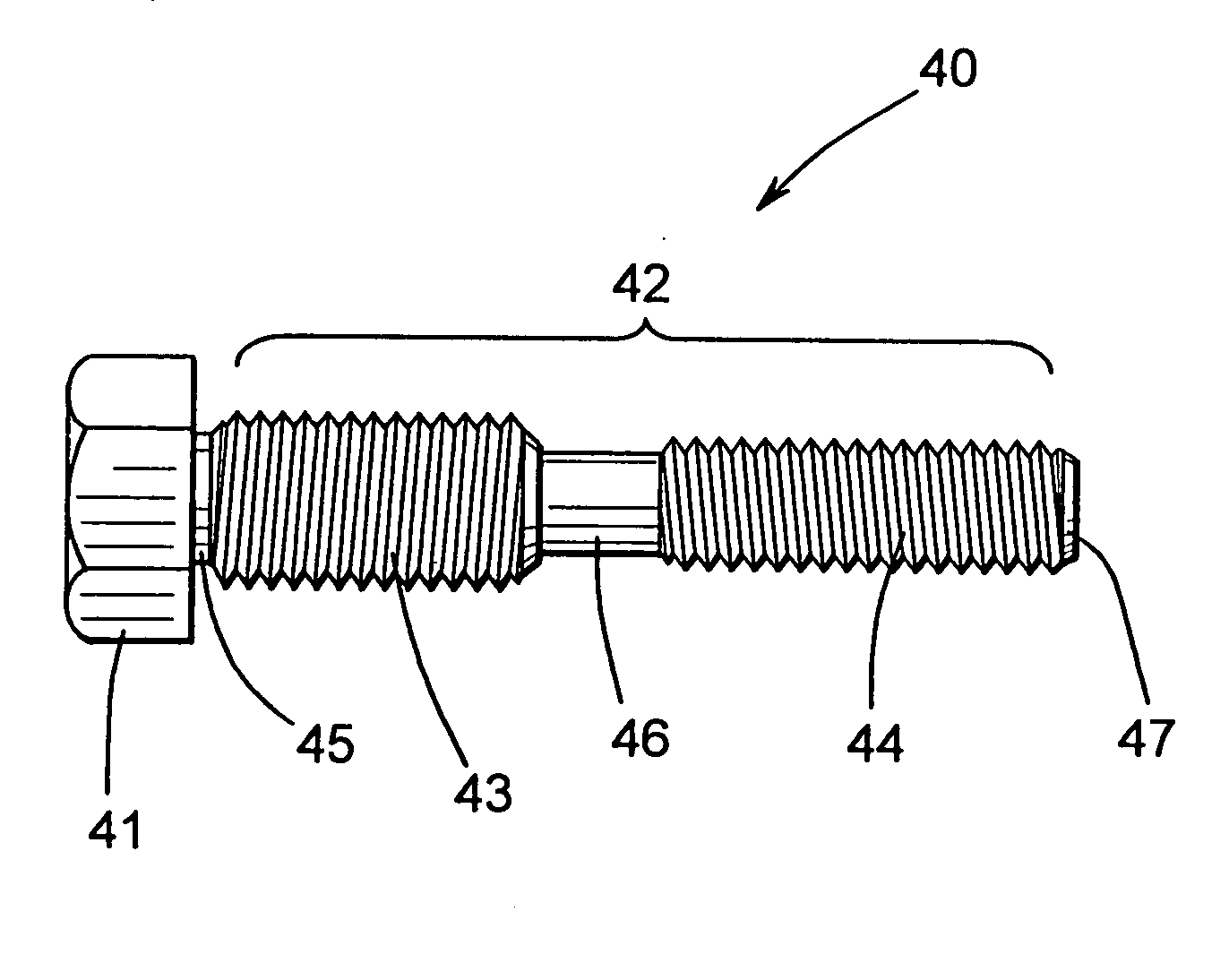
Fastener with opposite hand threads for securing two components together
a technology of fasteners and components, applied in the direction of threaded fasteners, screwing, couplings, etc., can solve the problems of insufficient resistance, awkwardness and difficulty, and further is relatively time-consuming, so as to achieve the effect of preventing rotation and improving the structur
- Summary
- Abstract
- Description
- Claims
- Application Information
AI Technical Summary
Benefits of technology
Problems solved by technology
Method used
Image

Examples
Embodiment Construction
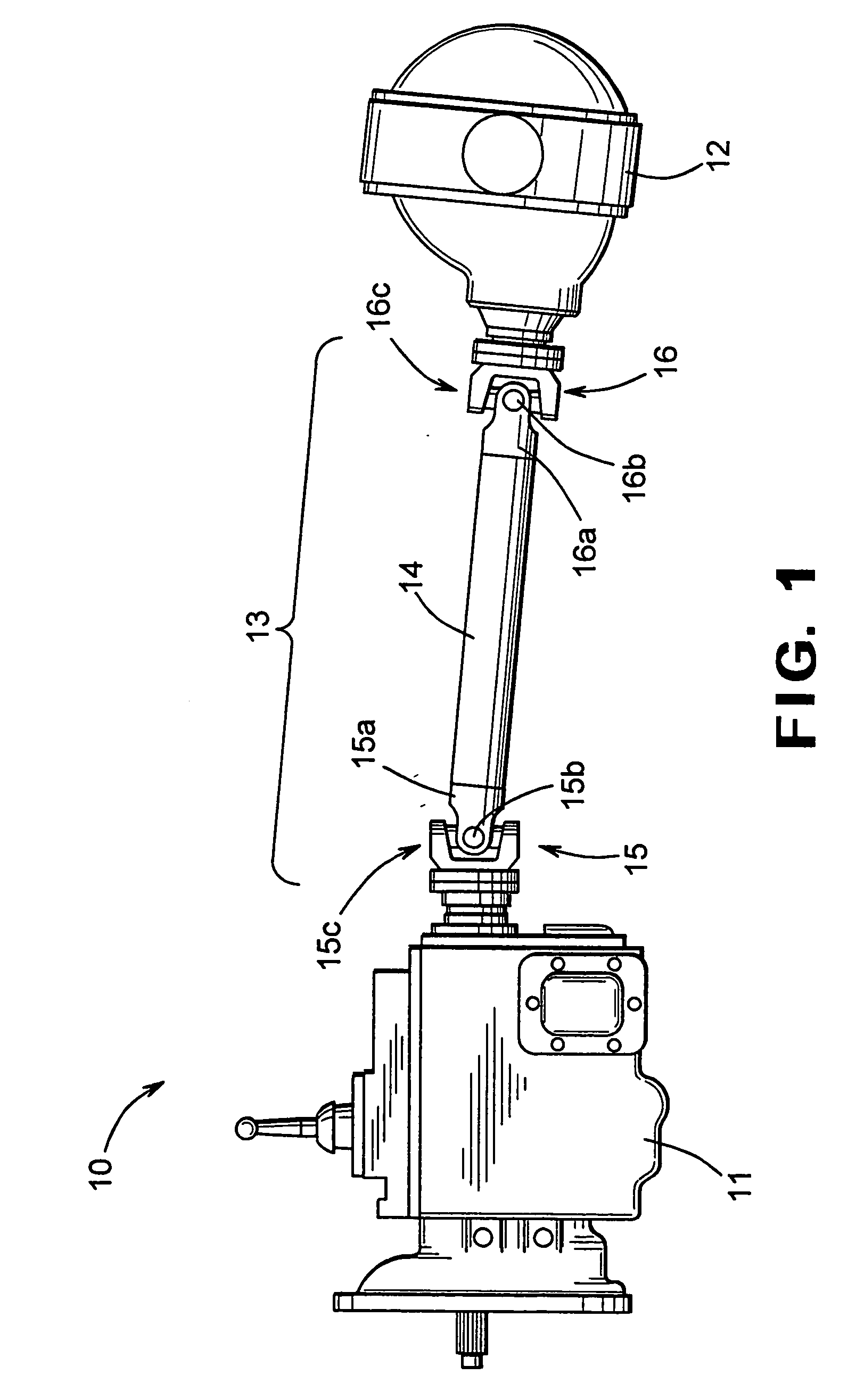
[0012] Referring now to the drawings, there is illustrated in FIG. 1 a vehicle drive train system, indicated generally at 10, in accordance with this invention. The illustrated vehicle drive train system 10 is, in large measure, conventional in the art and is intended merely to illustrate one environment in which this invention may be used. Thus, the scope of this invention is not intended to be limited for use with the specific structure for the vehicle drive train system 10 illustrated in FIG. 1 or with vehicle drive train systems in general. On the contrary, as will become apparent below, this invention may be used in any desired environment for the purpose of securing two components together.
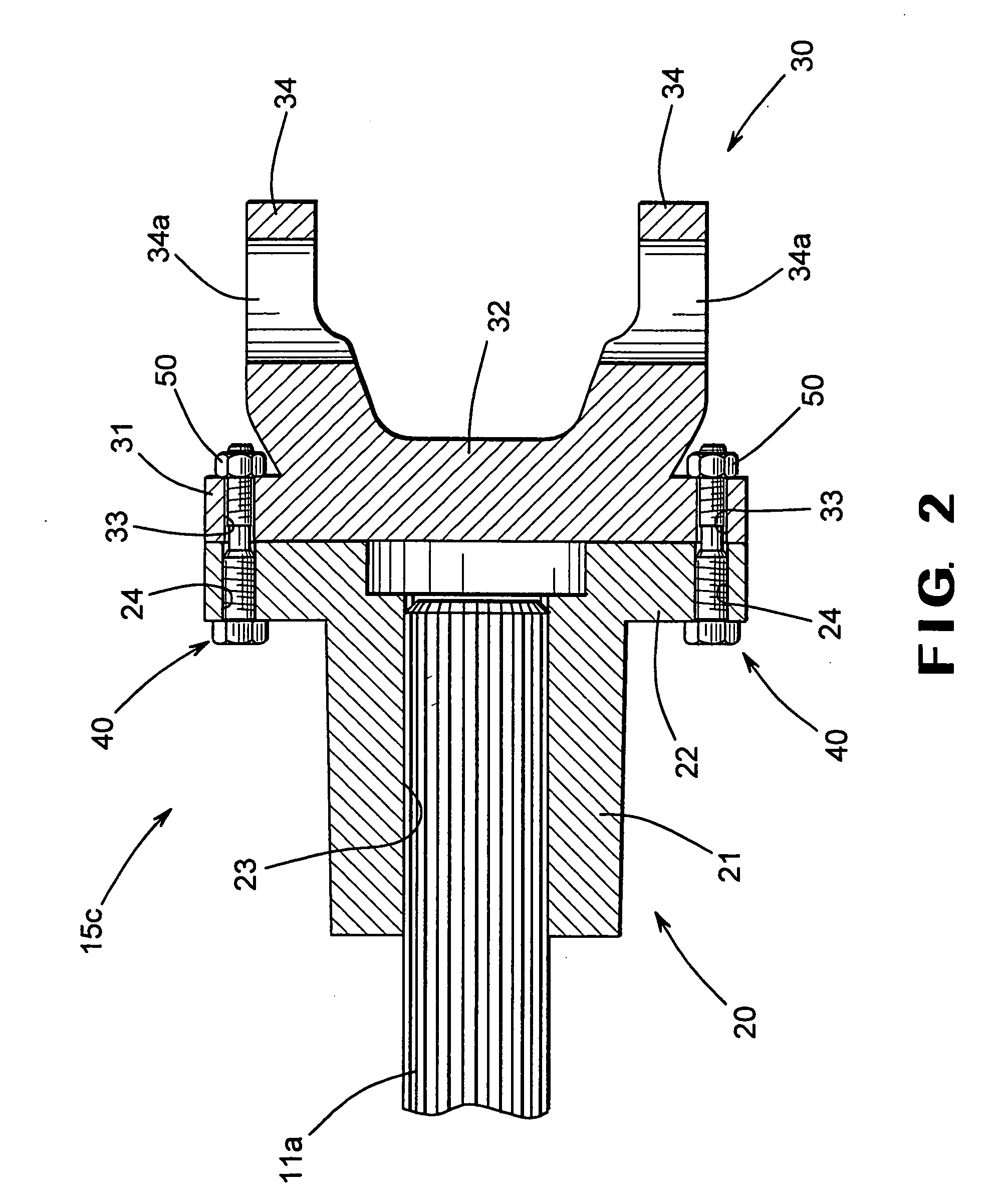
[0013] The illustrated drive train system 10 includes a transmission 11 having an output shaft (such as a male splined shaft 11a, as shown in FIG. 2) that is connected to an input shaft (not shown) of an axle assembly 12 through a driveshaft assembly 13. The transmission 11 is rotatably dri...
PUM
 Abstract
Description
Claims
Application Information