Rotating blade body and rotary machine using rotating blade body

Active Publication Date: 2005-09-22
MITSUBISHI HEAVY IND LTD
View PDF7 Cites 29 Cited by
  • Summary
  • Abstract
  • Description
  • Claims
  • Application Information

AI Technical Summary

Benefits of technology

[0026] In a rotating blade body in accordance with a preferred embodiment of the present invention, because movement and inclination of the rotating blades are restrained even during start-up operation and the like when the main shaft rotates at a low speed, the blade grooves and the blade roo

Problems solved by technology

In addition, because the position of the center of gravity of the rotating blade body itself varies repeatedly so as to cause unbalancing to the rotating blade body, inadvertent vibration is induced.
Furthermore, when local wear and deformation make a progress excessively in the blade grooves 20 and at the blade roots 10, an amount of movement or an amount of inclination of the rotating blades 1 becomes larger at a time of start-up and the like when the main shaft rotates at a low speed, so that further unbalancing is caused to the rotating blade body, resulting in higher vibration induced by this unbalancing.
Additionally, during a steady-state operation, because each of the rotating blades 1 is secured at a position drifting from the predetermined position, the position of the center of gravity of the rotating blade body itself varies, resulting in occurren

Method used


Image

  • Rotating blade body and rotary machine using rotating blade body
  • Rotating blade body and rotary machine using rotating blade body
  • Rotating blade body and rotary machine using rotating blade body

Examples


second embodiment

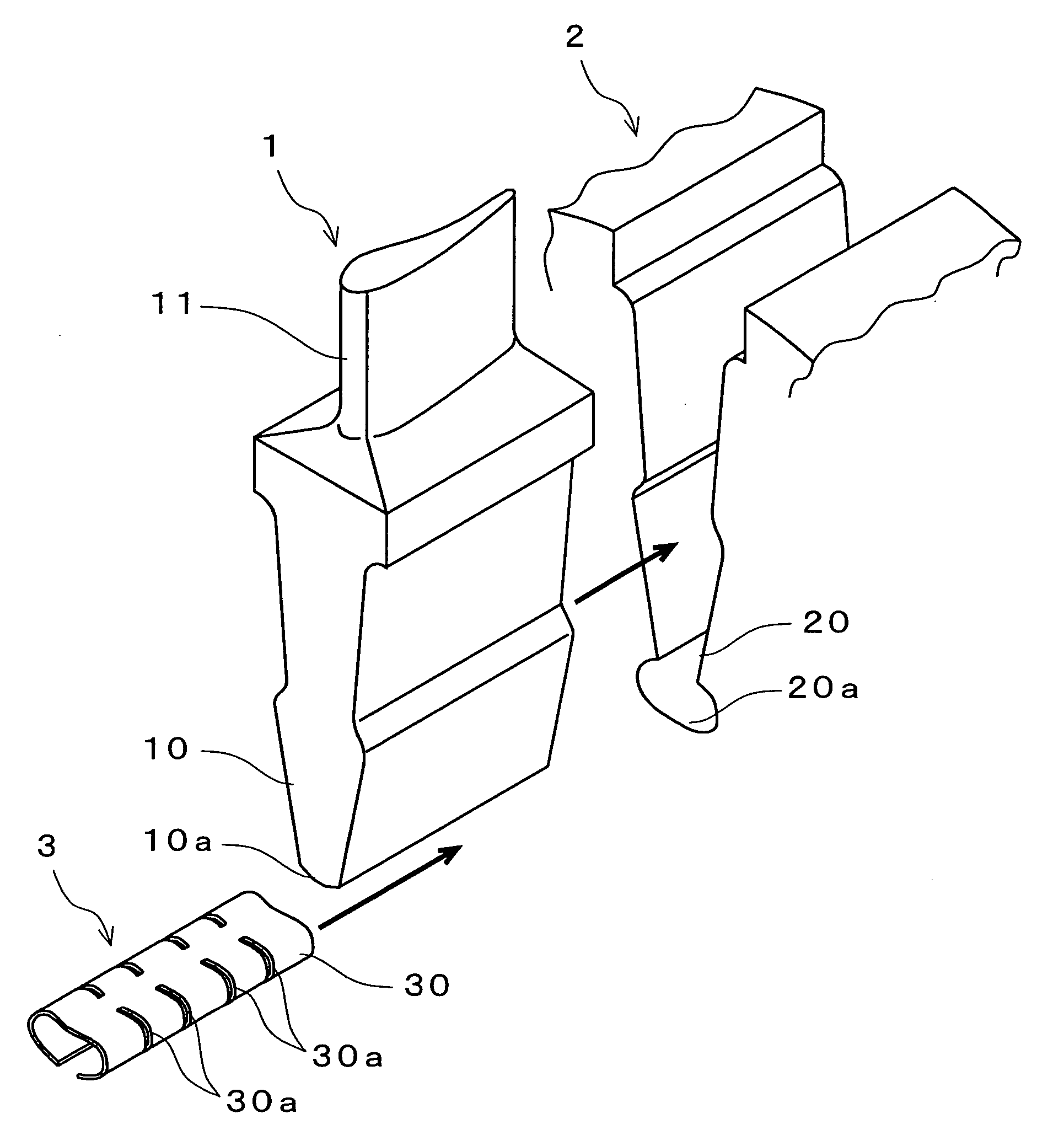
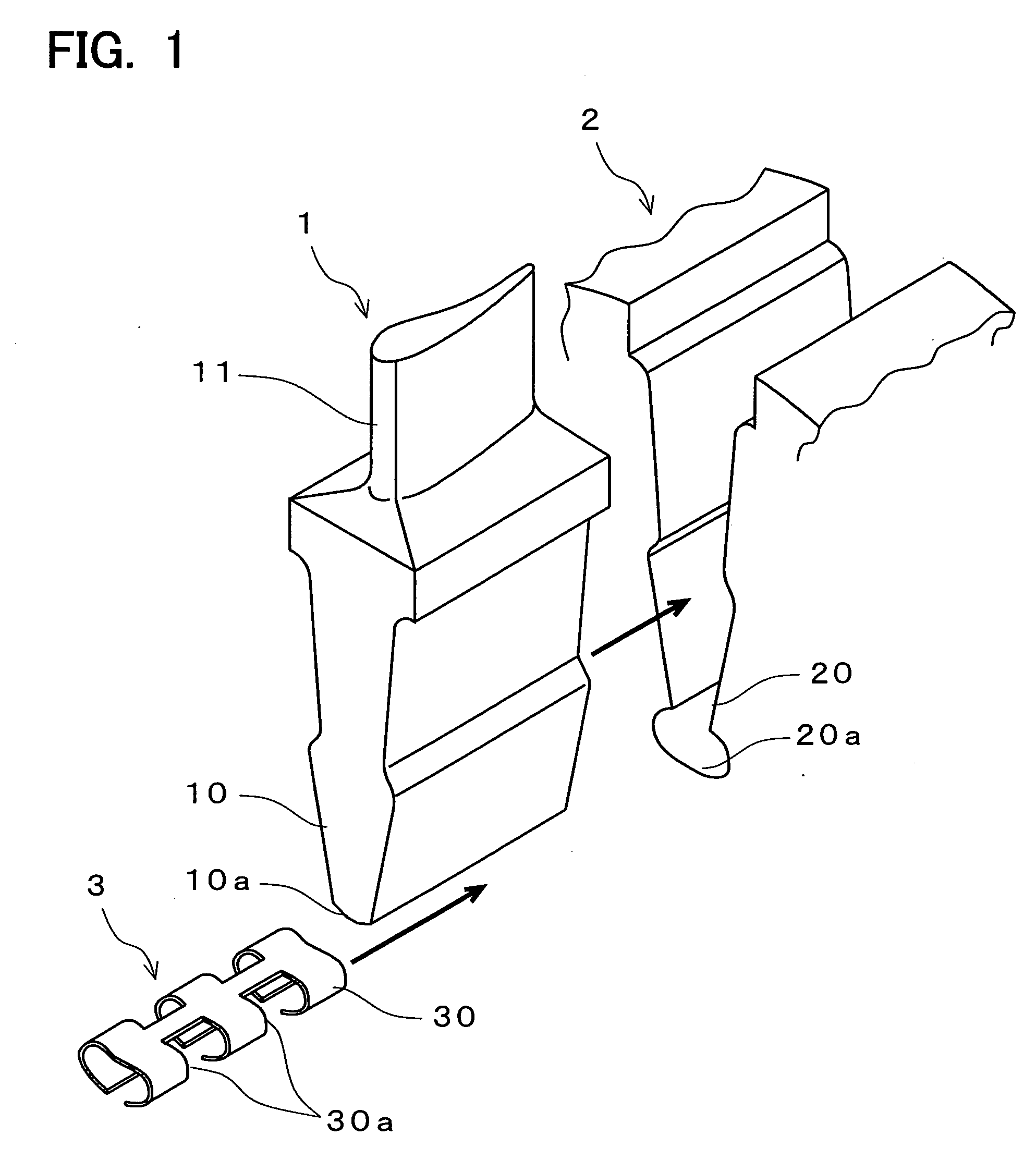
[0050] First, as shown in FIG. 5, the leaf springs 30′ in accordance with the present invention are formed so as to have both end portions thereof in a rotation direction of the rotating shaft be in contact with the side surfaces of the bottom portions 20a of blade grooves 20, get curved, rising up along the side surfaces and being in contact with the bottom-end portions 10a of blade root portions 10, and then, by getting curved further, have the middle portions come in contact with the bottom faces of the bottom portions 20a of the blade grooves 20.

third embodiment

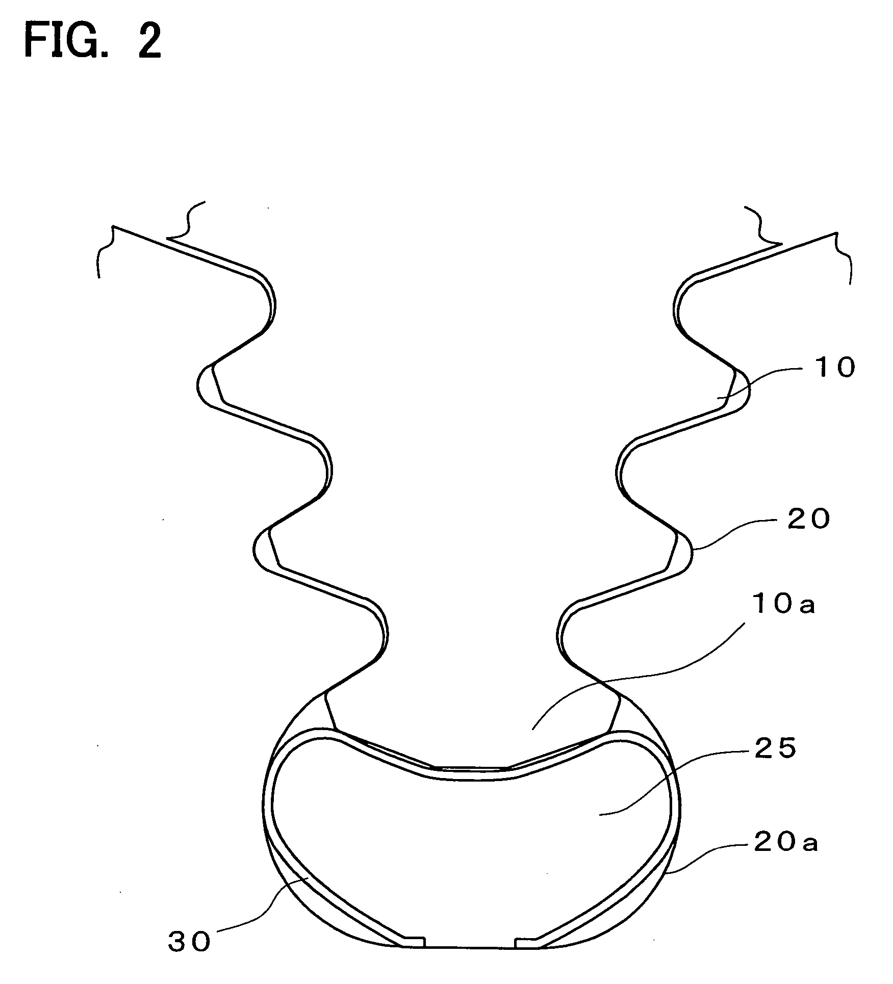
[0051] On the other hand, as shown in FIG. 6, the leaf springs 30″ in accordance with the present invention exist approximately along the outer edges of circulation spaces 25 and are formed so as to have approximately all areas in the rotation direction of the rotating shaft be in contact with the bottom portions 20a of the blade grooves 20 and have both end portions be in contact with the side surfaces of the bottom-end portions 10a of the blade root portions 10.

[0052] Next, a fourth embodiment of the present invention will be described, by referring to FIG. 7 and FIG. 8. FIG. 7 is an exploded perspective view of a rotating blade body in accordance with a fourth embodiment of the present invention, and FIG. 8 is a plan view of a necessary portion of the rotating blade body viewed in a direction of the rotating shaft. Characteristic of this fourth embodiment of the present invention is that construction of the pushing-up members 3 of the first embodiment of the present invention is ...

fourth embodiment

[0053] To put it plainly, in the present invention, metallic blocks 31 are engaged into the circulation spaces 25, serving as pushing-up members 3. This block 31 has a contour approximately being along the bottom-end portion 10a of a blade root portion 10 and the bottom portion 20a of a blade groove 20. However, in the neighborhood of both side surfaces of the bottom-end portion 10a of a blade root portion 10, cutout 31a is formed along the direction of the rotating shaft.


PUM


Abstract

Such a rotating blade body is supplied as can prevent not only local wear and deformation but also inadvertent vibration and can maintain cooling efficiency. A rotating blade body consists of a rotor disc 2 and rotating blades 1 which are assembled so as to extend from the outer circumference of the rotor disc 2 in a radial pattern, wherein blade root portions 10 of the rotating blades 1 are engaged into blade grooves 20 which are formed along a direction of a rotating shaft on an edge of the outer circumference of the rotor disc 2. Circulation spaces 25 for the cooling air are formed along the direction of a rotating shaft between the bottom-end portions 10a of the blade root portions 10 and the bottom portions 20a of the blade grooves 20. Pushing-up members 3 which push up the rotating blades 1 outward in a radial direction are inserted into the circulation spaces 25, maintaining circulation of the cooling air.

Description

[0001] The present invention is based on the Japanese Patent Application No. 2004-049589 applied on Feb. 25, 2004 and the Japanese Patent Application No. 2004-209462 applied on Jul. 16, 2004. BACKGROUND OF THE INVENTION [0002] 1. Field of the Invention [0003] The present invention relates to a rotating blade body, which is mounted to a rotary machine such as a turbine part of a gas turbine, steam turbine, jet engine and the like or an air compressor of a gas turbine and jet engine and rotates with a main shaft in an integrated manner, and relates to a rotary machine to which a rotating blade body is installed. [0004] 2. Description of the Prior Art [0005] Generally, in a rotary machine such as a turbine part of a gas turbine and the like and an air compressor, a main shaft is installed inside a casing constructing an outer shape so as to achieve axial rotation. Rotor discs are installed to this main shaft in a plurality number of stagesaxially, and a plurality number of pieces of ro...

Claims


Application Information

Patent Timeline
IPC IPC(8): F01D5/14F01D5/30F01D5/18F01D5/32F02C7/18F04D29/34F04D29/58
CPCF01D5/081F01D5/3007Y10S416/50Y02T50/676Y02T50/671Y02T50/60
Inventor KANEBAKO, ATSUHIKOOJIRO, YASUHIROAKAGI, KOUICHITAKAMURA, KEITA
Owner MITSUBISHI HEAVY IND LTD
Why Eureka
Try Eureka