Test tube holder

Active Publication Date: 2005-09-22
IDS CO LTD
View PDF6 Cites 39 Cited by
  • Summary
  • Abstract
  • Description
  • Claims
  • Application Information

AI Technical Summary

Benefits of technology

[0009] The present invention provides a test tube holder which has a simpler

Problems solved by technology

In the above test holder, the elasticity of the leaf springs is compensated for by the O-ring, and the structures of the leaf springs and peripheral members thereof are complicated.
Thus,

Method used


Image

  • Test tube holder
  • Test tube holder
  • Test tube holder

Examples


Example

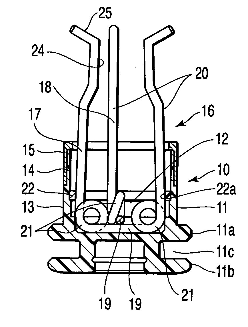
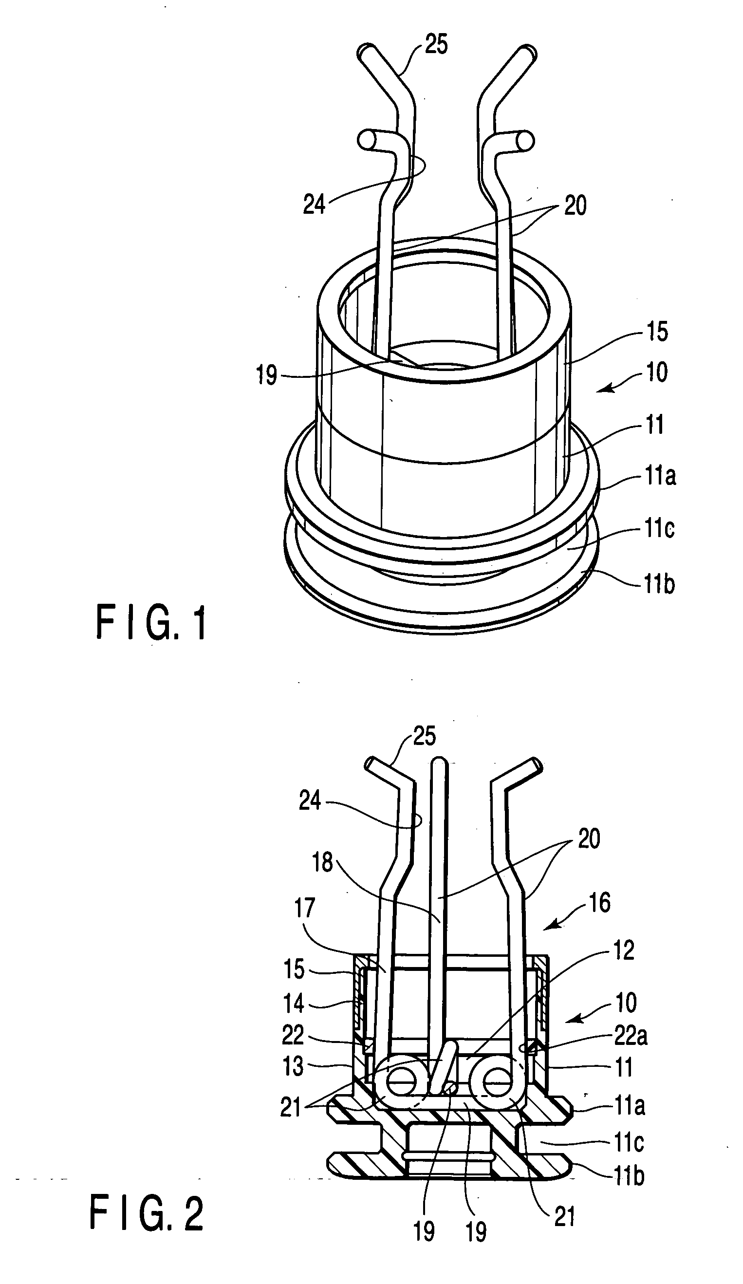
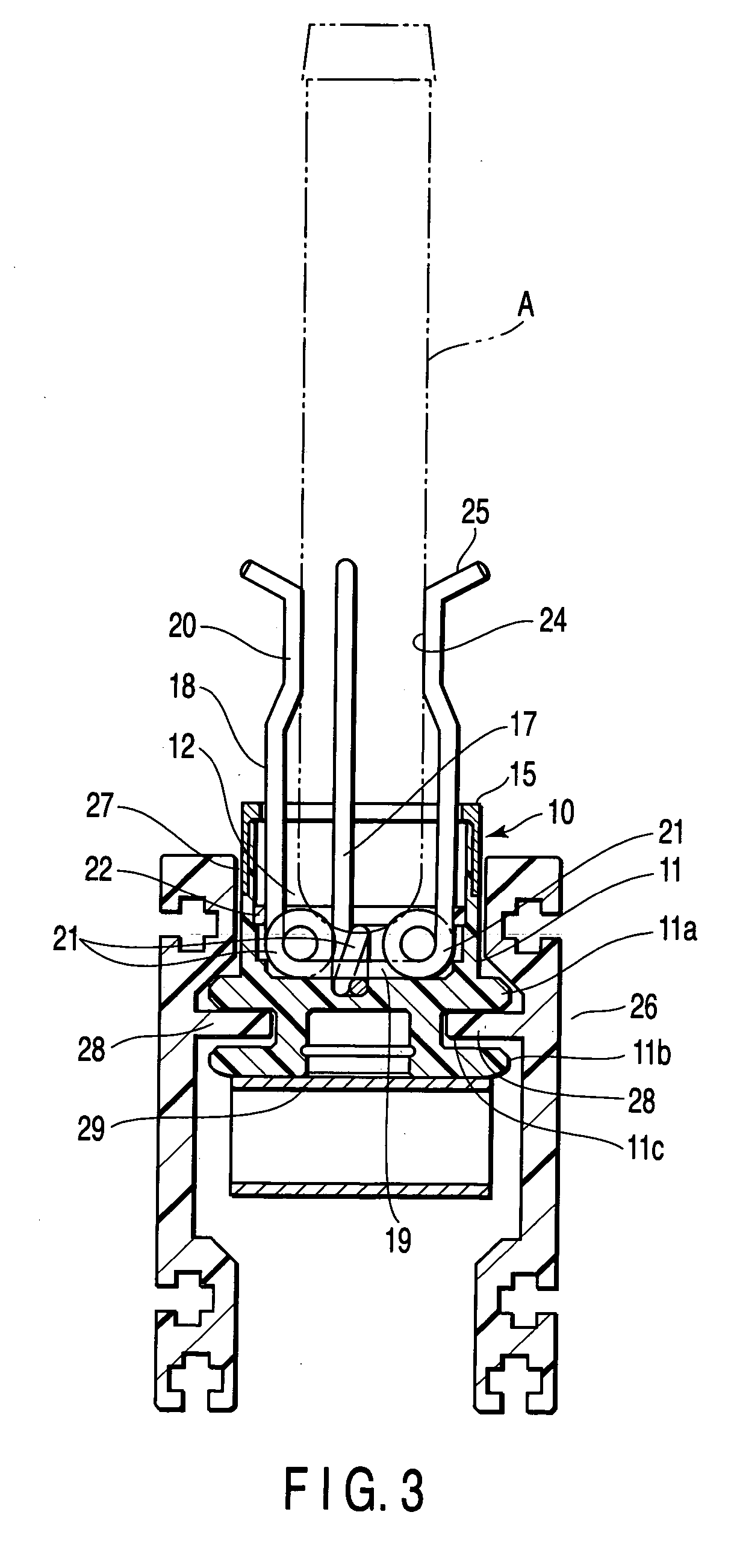
[0019] A test tube holder 1 according to an embodiment of the present invention will be explained with reference to FIGS. 1 to 3. The test tube holder 1 has a main body 10 and an adapter 16. The main body 10 is formed of a synthetic resin material. Flange portions 11a and 11b are formed at an outer peripheral surface of a proximal end portion of a cylindrical base body 11 of the main body 10. They are vertically arranged at two stages. Therefore, an annular groove 11c is provided between the flange portions 11a and 11b. As shown in FIG. 3, convex portions 28 of a conveyor rail 26 are fitted in the annular groove 11c between the flange portions 11a and 11b.

[0020] A cylindrical hollow portion 12 for accommodating a test tube is formed in a center portion of the cylindrical base body 11 to extend from an upper end portion thereof to a depth corresponding to the position of the flange portion 11a at the upper stage. A central portion of the cylindrical base body 11 in the longitudinal ...


PUM


Abstract

A test tube holder includes a main body and an adapter. The main body includes a cylindrical hollow portion for accommodating a test tube. The adapter is provided in the cylindrical hollow portion to hold the test tube. The adapter includes bottom portions, holding portions and loop portions, which are U-shaped as a whole. The bottom portions are located to cross the center axis of the cylindrical hollow portion. The loop portions are provided at the ends of the bottom portions, and coiled at least one. The holding portions are continuous with the loop portions and the bottom portions. The bottom portions of first and second spring steel wires are provided in the cylindrical hollow portion to intersect with each other. The holding portions of the first and second spring steel wires are projected upwards from the cylindrical hollow portion.

Description

CROSS-REFERENCE TO RELATED APPLICATIONS [0001] This application is based upon and claims the benefit of priority from prior Japanese Patent Application No. 2004-075947, filed Mar. 17, 2004, the entire contents of which are incorporated herein by reference. BACKGROUND OF THE INVENTION [0002] 1. Field of the Invention [0003] This invention relates to a test tube holder for use in carriage of a test tube containing a specimen such as blood. [0004] 2. Description of the Related Art [0005] A test tube containing a specimen such as blood is formed of transparent glass or plastic. A cap formed of rubber or synthetic resin is put on an upper opening portion of the test tube. The test tube is carried to each of processing sections, while being vertically held by a test tube holder and guided along a carrier passage, in order that the specimen contained in the test tube be served or poured into another test tube. [0006] Therefore, the test tube holder is formed to stably and vertically hold e...

Claims


Application Information

Patent Timeline
IPC IPC(8): A61J1/16G01N1/00B01L9/00B01L9/06G01N1/10
CPCG01N35/04B01L9/06
Inventor ITOH, TERUAKI
Owner IDS CO LTD
Why Eureka
Try Eureka