Catalytic converter with integral heat shield device

a heat shield device and catalytic converter technology, applied in machines/engines, separation processes, other domestic objects, etc., can solve the problems of poor shielding and insulation, and the heat shield typically does not completely cover, so as to reduce harmful emissions

Inactive Publication Date: 2005-09-22
INT MUFFLER
View PDF9 Cites 11 Cited by
  • Summary
  • Abstract
  • Description
  • Claims
  • Application Information

AI Technical Summary

Benefits of technology

[0006] In this manner, the present invention provides a catalytic converter and heat shield having a shape more suitable for packaging on the underside of the vehicle, which has a diameter that is not much larger than the tube diameter of the rest of the exhaust system. The inventive manufacturing process provides a catalytic converter with a heat shield that does not require attachment to the catalytic converter in a separate step during the manufacturing process. The inventive heat shield better insulates the catalyst providing earlier light off, reducing harmful emissions.

Problems solved by technology

The heat shield typically does not entirely enclose the portion of the catalytic converter containing the catalysts providing poor shielding and insulation.

Method used


Image

  • Catalytic converter with integral heat shield device
  • Catalytic converter with integral heat shield device

Examples


Embodiment Construction

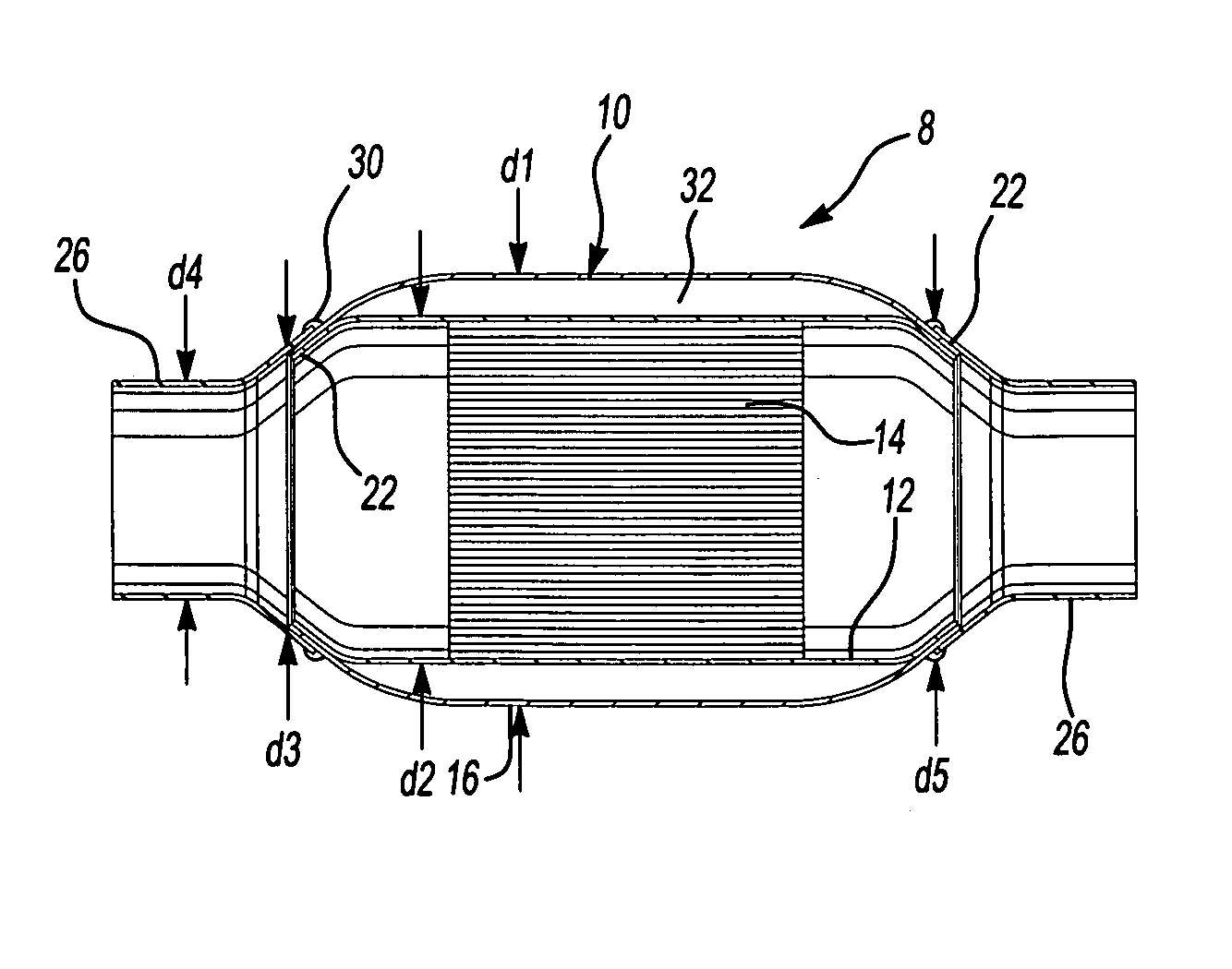
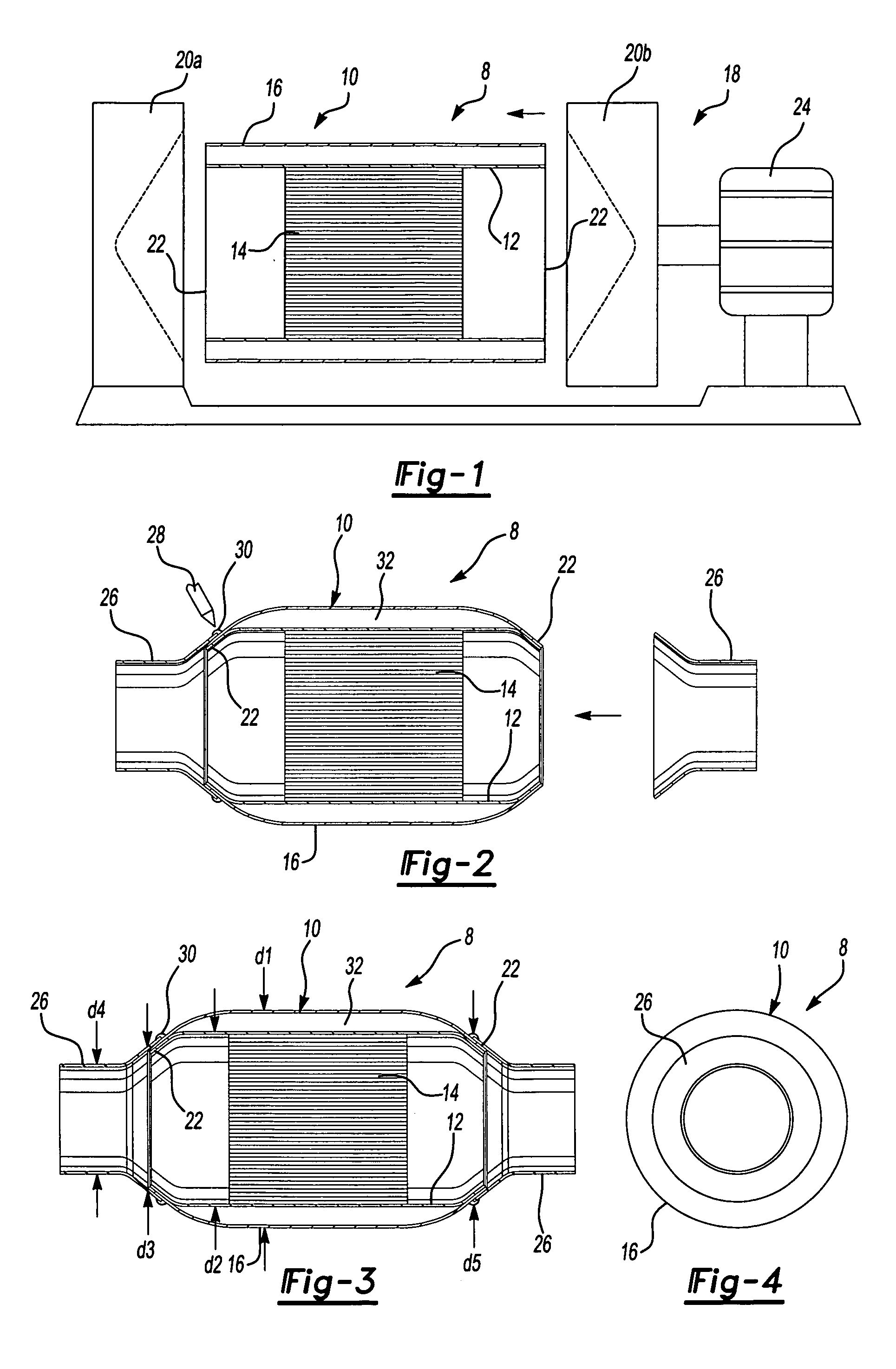
[0012] An example of the inventive manufacturing process for the catalytic converter of the present invention is schematically shown in FIG. 1. The catalytic converter 8 includes a center portion 10 having an inner liner 12 housing a catalyst or substrate 14. An outer liner 16 is arranged about the inner liner 12 so that there is space between the liners 12 and 16. The liners 12 and 16 preferably have a circular cross-section and are cylindrical in shape. Furthermore, it is preferable that the liners 12 and 16 are of approximately the same length.

[0013] The center portion 10 is arranged between opposing dies 20 of a forming machine 18. The dies 20 have a generally conical recess, but may be of any suitable shape, as will be appreciated by one of ordinary skill in the art. The dies 20 are moved towards one another to plastically deform opposing ends 22 of the center portion 10 inwardly. As the ends 22 are being deformed, the inner liner 12 becomes centered relative to the outer line...


PUM

PropertyMeasurementUnit
temperaturesaaaaaaaaaa
shapeaaaaaaaaaa
lengthaaaaaaaaaa

Abstract

A catalytic converter includes an inner liner housing a catalyst and an outer liner concentric with the inner liner. In one example, the liners are cylindrical tubes arranged between opposing dies during manufacture. The dies are moved toward one another to plastically deform the ends inwardly to form a conical flange. The forming process provides a sealed cavity between the walls of the inner and outer liners that insulates the hot catalyst housed within the inner liner from the environment exterior of the catalytic converter assembly. First and second tapered connecting tubes are welded onto the opposing ends of the catalytic converter in the area of the flange.

Description

BACKGROUND OF THE INVENTION [0001] This invention relates to a catalytic converter with a heat shield and method of forming a catalytic converter integral with a heat shield. [0002] Catalytic converters are used to reduce harmful emissions from vehicle exhaust. Catalytic converters reach high temperatures, up to 400° C. or more, to achieve the desired chemical reactions necessary to reduce harmful products of combustion. The sooner the catalytic converter reaches the desired operating temperature, the sooner the catalyst can begin converting the product of combustion. Since the catalytic converter reaches high temperatures, it must be insulated from other portions of the vehicle that may be harmed by the heat typically by using a heat shield. [0003] A typical prior art catalytic converter includes two halves that are secured to one another at a seam forming a flange extending about the perimeter of the catalytic converter. This type of configuration results in a relatively flat and ...

Claims


Application Information

Patent Timeline
Patent Type & Authority Applications(United States)
IPC IPC(8): B01D53/34F01N3/20F01N3/28F01N13/14
CPCF01N3/2006F01N3/2842F01N13/14Y10T29/49345F01N2450/02F01N2450/22F01N13/143
Inventor BORNEBY, HANS
Owner INT MUFFLER
Why Eureka
Try Eureka