Substrate heating device and manufacturing method for the same

a heating device and substrate technology, applied in the direction of heater elements, hot plate heating arrangements, instruments, etc., can solve the problem of difficult to achieve an extremely high level of temperature uniformity based on the conventional design adjustment of resistance heating elements or tubular members, and achieve the effect of high accuracy

Active Publication Date: 2005-09-29
NGK INSULATORS LTD
View PDF3 Cites 3 Cited by
  • Summary
  • Abstract
  • Description
  • Claims
  • Application Information

AI Technical Summary

Benefits of technology

[0016] According to the substrate heating device, the tubular member is ground, and due to that grinding, the heat transfer from the tubul

Problems solved by technology

Correction of slight differences in temperature distribution based on the conventional design adjustments for resistan

Method used


Image

  • Substrate heating device and manufacturing method for the same
  • Substrate heating device and manufacturing method for the same
  • Substrate heating device and manufacturing method for the same

Examples


first working example

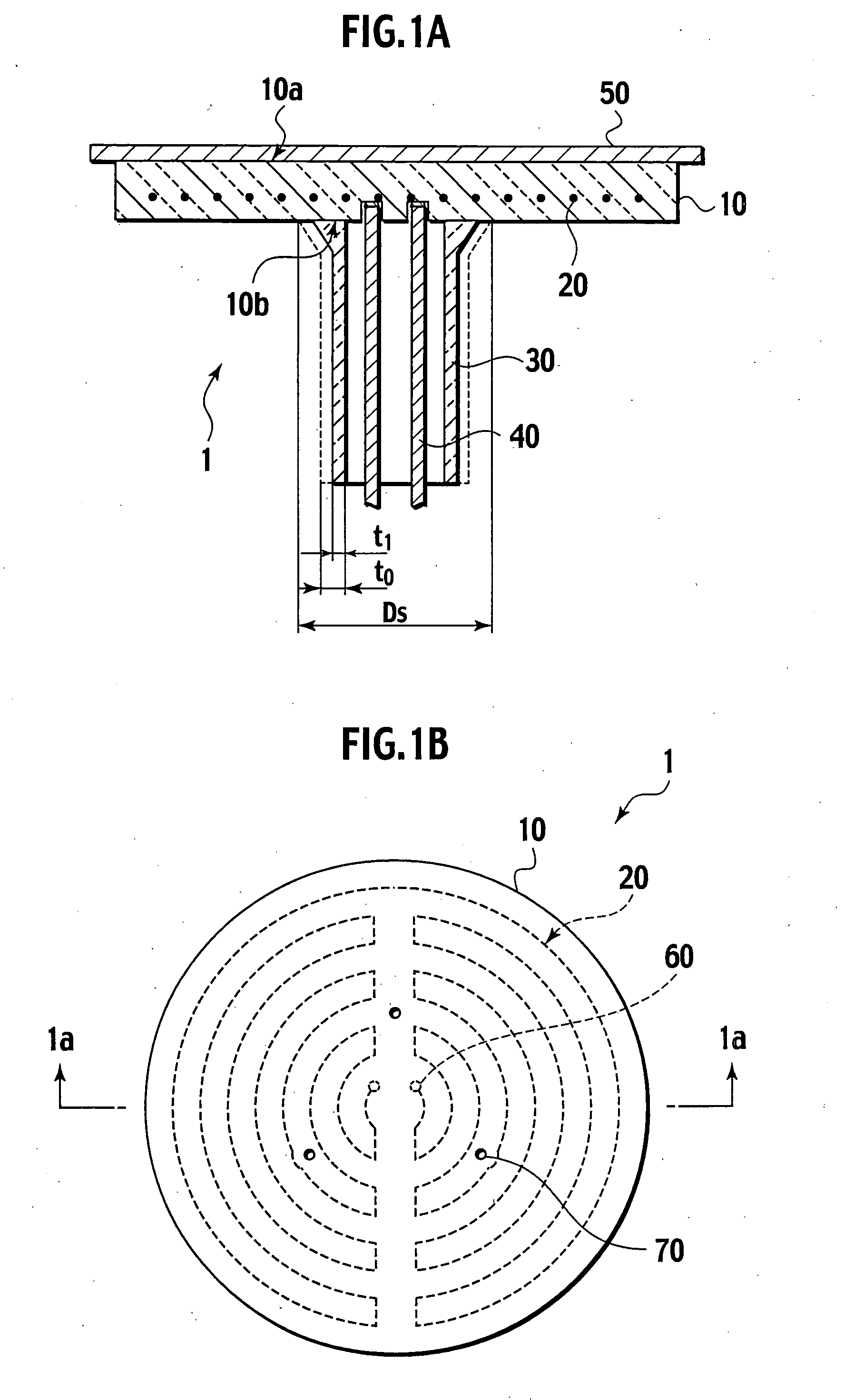
[0085] The ceramic base plate 10 in which the resistance heating element 20 are buried is formed under the following conditions. An acrylic resin binder is added to a ceramic mixed powder, which is made by adding 5% by weight of Y2O3 to an AlN powder obtained through reductive nitridation, and granules are then generated through spray granulation. These granules are filled in a mold and pressed so as to form a preform. Next, a channel is formed at positions for the resistance heating element 20 of the preform to be buried by transcription. Linear Mo resistance heating element 20 0.5 mm in diameter processed in the shape shown in FIG. 1B is placed in the channel, the ceramic raw powder is filled thereupon, and the entirety is re-pressed in a uniaxial direction. The pressing pressure is 200 kg / cm2. This forms the ceramic compact for the base plate 10 in which the resistance heating element20 is buried.

[0086] The ceramic compact is sintered using a hot pressing method. Sintering condi...

second working example

[0097] A preliminary unit for the substrate heating device 1 made up of an aluminum nitride base plate 10 and the tubular member 30 is formed. The external diameter of the base plate 10 is 340 mm, and the thickness is 15 mm. Furthermore, as shown in FIG. 3B, two types of resistance heating element 20a, 20b are buried in the base plate 10 so as to be a two-layer structure parallel to the substrate heating surface 10a. The upper layer resistance heating element 20a is buried at a depth of 6.5 mm from the substrate heating surface 10a, and the lower layer resistance heating element 20b is buried at a depth of 12 mm from the substrate heating surface 10a. The external diameter of the junction 10b of the tubular member 30 obtained by sintering is 90 mm, the external diameter of the tubular member 30 in the middle of the axis is 58 mm with thickness t0 of 3.5 mm, and the length thereof is 220 mm. The manufacturing conditions other than those above are the same as in the first working exam...


PUM

PropertyMeasurementUnit
Thicknessaaaaaaaaaa
Temperatureaaaaaaaaaa
Thicknessaaaaaaaaaa

Abstract

A manufacturing method for a substrate heating device comprises forming a base plate having a substrate heating surface in which a resistance heating element is buried, forming a tubular member, joining the tubular member to the base plate, measuring temperature distribution in the substrate heating surface by supplying power to the resistance heating element, and grinding the tubular member according to a grinding condition based on a measurement result of the temperature distribution.

Description

CROSS REFERENCE TO RELATED APPLICATIONS [0001] This application is based upon and claims the benefit of priority from prior Japanese Patent Application No.P2004-49699, filed on Feb. 25, 2004; the entire contents of which are incorporated herein by reference. BACKGROUND OF THE INVENTION [0002] 1. Field of the Invention [0003] The present invention relates to a substrate heating device, which heats a substrate such as a semiconductor wafer, a liquid crystal substrate or the like, and a manufacturing method for the same. More specifically, the present invention relates to a substrate heating device with a resistance heating element buried in a ceramic or metallic base plate, and a manufacturing method for the same. [0004] 2. Description of the Related Art [0005] A heater with a resistance heating element buried in a ceramic or metallic base plate is widely used as a substrate heating device used for semiconductor manufacturing apparatus or the like. For example, a ceramic heater with a...

Claims


Application Information

Patent Timeline
IPC IPC(8): H05B3/06G01F1/68H01L21/00H01L21/02H01L21/205H01L21/3065H01S4/00H05B3/10H05B3/74
CPCH01L21/67103Y10T29/49098Y10T29/49096Y10T29/49083Y10T29/49085Y10T29/49002Y10T29/49087
Inventor UNNO, YUTAKAGOTO, YOSHINOBUKIKU, TAIJI
Owner NGK INSULATORS LTD
Why Eureka
Try Eureka