
Signal processing apparatus and method, recording medium and program

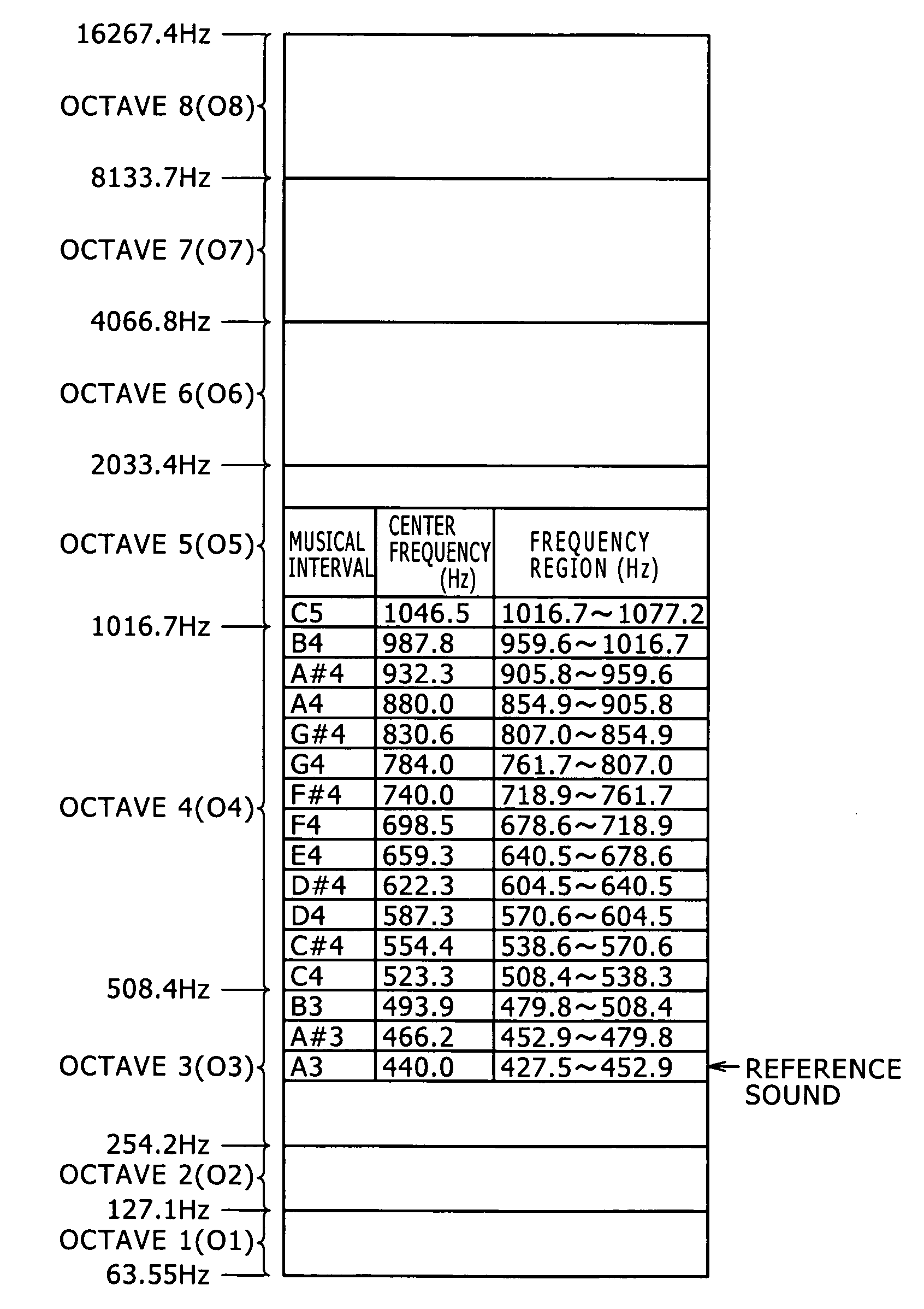
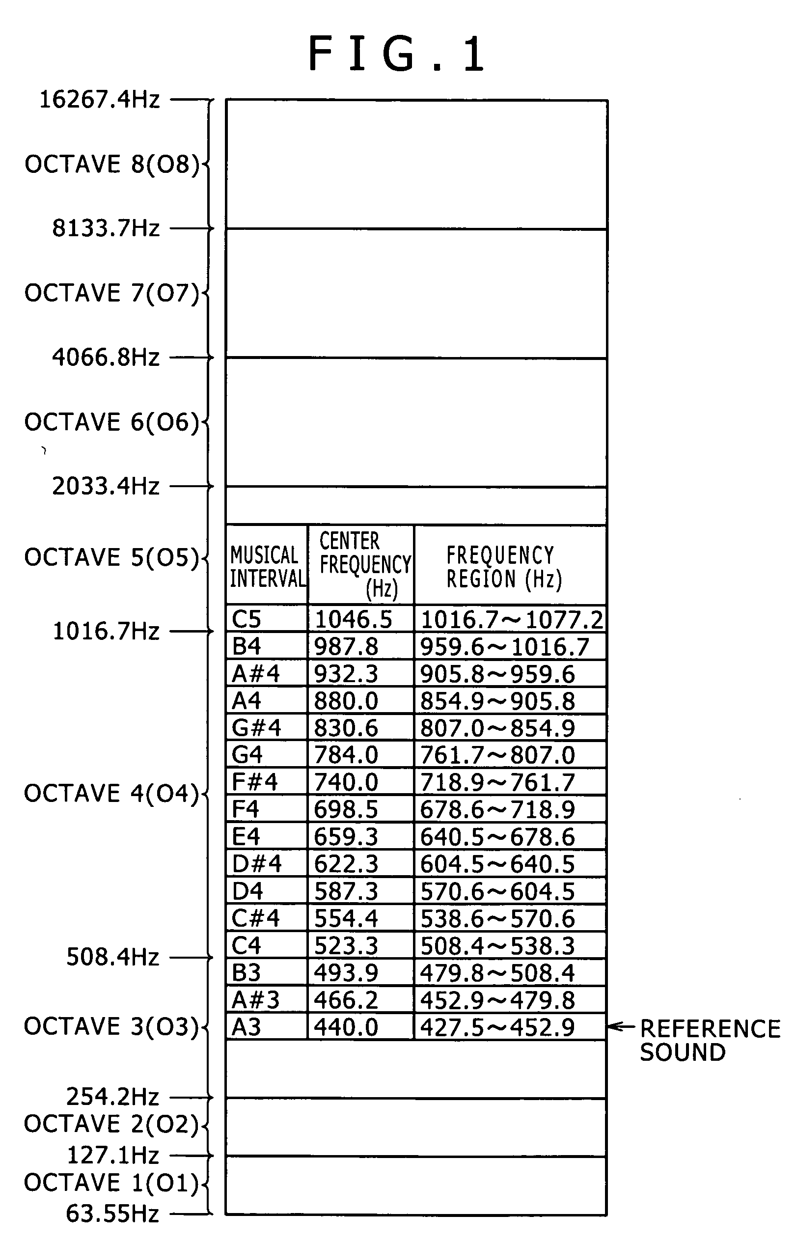
a signal processing and recording medium technology, applied in the field of signal processing apparatus and method, a recording medium and a program, can solve the problems of insufficient frequency resolution on the low frequency region side but is excessive, time resolution becomes excessive on the low frequency region side, and insufficient time resolution on the high frequency region sid

Inactive Publication Date: 2005-09-29
SONY CORP
View PDF35 Cites 23 Cited by
  • Summary
  • Abstract
  • Description
  • Claims
  • Application Information

AI Technical Summary

Benefits of technology

[0013] It is an object of the present invention to provide a signal processing apparatus and method, a recording medium and a program by which signal components of different musical intervals of an audio signal can be obtained with a small amount of arithmetic operation.

Problems solved by technology

Therefore, according to a musical interval estimation method which uses the short-time Fourier transform, there is a tendency that the frequency resolution is insufficient on the low frequency region side but is excessive on the high frequency region side.
On the other hand, if it is tried to assure a sufficient frequency resolution on the low frequency region side, then the time resolution becomes excessive on the low frequency region side.
On the contrary, if it is tried to assure a sufficient and necessary frequency resolution on the high frequency region side, then the time resolution becomes insufficient on the high frequency region side.
Due to the non-linear process, the musical interval estimation method which uses the short-time Fourier transform has a problem that the process is complicated.
However, where the method which uses the wavelet conversion or a BPF bank is applied, for example, to analysis of musical intervals for the overall audio frequencies, a very great amount of arithmetic operation is required, and therefore, the methods are poor in practical use.

Method used


Image

  • Signal processing apparatus and method, recording medium and program
  • Signal processing apparatus and method, recording medium and program
  • Signal processing apparatus and method, recording medium and program

Examples


Embodiment Construction

[0035] Before the best mode for carrying out the present invention is described in detail, a corresponding relationship between several features recited in the accompanying claims and particular elements of the preferred embodiment described below is described. It is to be noted, however, that, even if some mode for carrying out the invention which is recited in the specification is not described in the description of the corresponding relationship below, this does not signify that the mode for carrying out the invention is out of the scope or spirit of the present invention. On the contrary, even if some mode for carrying out the invention is described as being within the scope or spirit of the present invention in the description of the corresponding relationship below, this does not signify that the mode is not within the spirit or scope of some other invention than the present invention.

[0036] Further, the following description does not signify all of the invention disclosed in...


PUM


Abstract

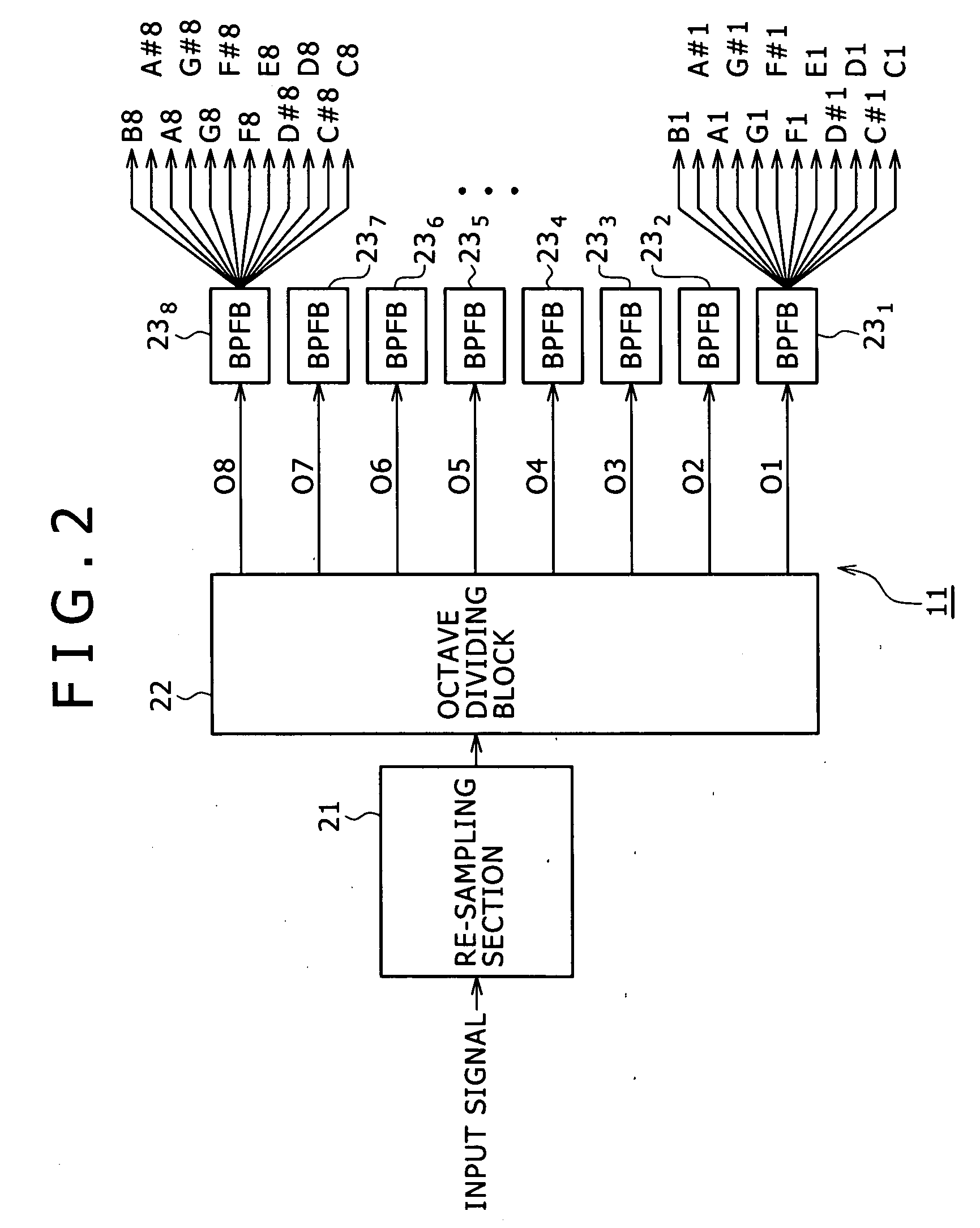
A signal processing apparatus and method is disclosed by which signal components of different musical intervals of an audio signal can be obtained with a small amount of arithmetic operation. A re-sampling section re-samples an audio signal inputted thereto with a sampling frequency equal to a power-of two times a frequency at a boundary of an octave. An octave dividing block divides the audio signals outputted from the re-sampling section into audio signals of octaves and outputs the resulting audio signals to respective band-pass filter banks. Each of the band-pass filter banks includes 12 band-pass filters and extracts and outputs audio signals of 12 musical intervals from the audio signals of one octave. The invention can be applied to a signal processing apparatus which analyzes, for example, signal components of musical intervals of an audio signal.

Description

BACKGROUND OF THE INVENTION [0001] This invention relates to a signal processing apparatus and method, a recording medium and a program, and more particularly to a signal processing apparatus and method, a recording medium and a program by which signal components of different musical intervals of an audio signal can be obtained. [0002] Various musical interval estimation methods have been proposed wherein signal components obtained by sampling a digital audio (music) signal with a predetermined sampling frequency are classified into signal components of different musical intervals (scales) such as, for example, C, C#, D, D#, E, F, F#, G, G#, A, A# and B (which correspond to do, do#, re, re#, mi, fa, fa#, so, so#, la, la# and ti, respectively). Such estimation of musical intervals of an audio signal is utilized, for example, for automatic music transcription, music analysis (melody analysis) and so forth. [0003] The twelve musical intervals of C, C#, D, D#, E, F, F#, G, G#, A, A# and...

Claims


Application Information

Patent Timeline
IPC IPC(8): G10L25/00G10G3/04G10G7/02G10H1/00G10H1/12G10H5/00G10L25/90H03H7/01H03H17/02
CPCG10G3/04G10H1/0008H03H17/0266G10H2210/066G10H2250/631G10H1/12
Inventor KOBAYASHI, YOSHIYUKI
Owner SONY CORP
Learn More