Control valve apparatus

a technology of control valves and apparatuses, which is applied in the direction of liquid transfer devices, machines/engines, process and machine control, etc., can solve the problem of slow transmission startup operation

Active Publication Date: 2005-09-29
GM GLOBAL TECH OPERATIONS LLC
View PDF12 Cites 37 Cited by
  • Summary
  • Abstract
  • Description
  • Claims
  • Application Information

AI Technical Summary

Benefits of technology

[0013] The present invention will permit the parallel hybrid transmission with two or more modes to be completely powered from energy storage devices, an electric pump, and a torque-transmitting mechanism, which are incorporated into a conventional parallel hybrid transmission control system. The electric pump supplies oil to the torque-transmitting mechanism during full electric operation and a control valve transitions feed to the torque-transmitting mechanism between the engine pump and the electric pump. The control valve is actuated as pressure from the electric pump is supplied.
[0014] Under normal operating conditions, when the vehicle engine is running, a mechanical pump connected with the engine supplies oil to operate the power transmission torque-transmitting mechanism. The oil from the engine pump flows to the hydraulic controls, which regulates the oil pressure and delivers oil to the various systems of the transmission. When a particular range is commanded, oil is sent from the hydraulic control through the valve apparatus and then to the torque-transmitting mechanism. During this operating procedure, the electric pump is not used and the control valve is in a closed position, which permits engine-supplied oil to be delivered to the torque-transmitting mechanism. A pressure switch within the feed line issues a diagnostic check signal that the torque-transmitting mechanism is receiving pressurized fluid.

Problems solved by technology

However, when the engine operation is discontinued, the control fluid for the transmission is also discontinued which can result in slower startup operation of the transmission and / or require one of the electric drive motors to also drive a pump which would require the drive motor to be operated during these operating conditions.

Method used


Image

  • Control valve apparatus
  • Control valve apparatus
  • Control valve apparatus

Examples


Embodiment Construction

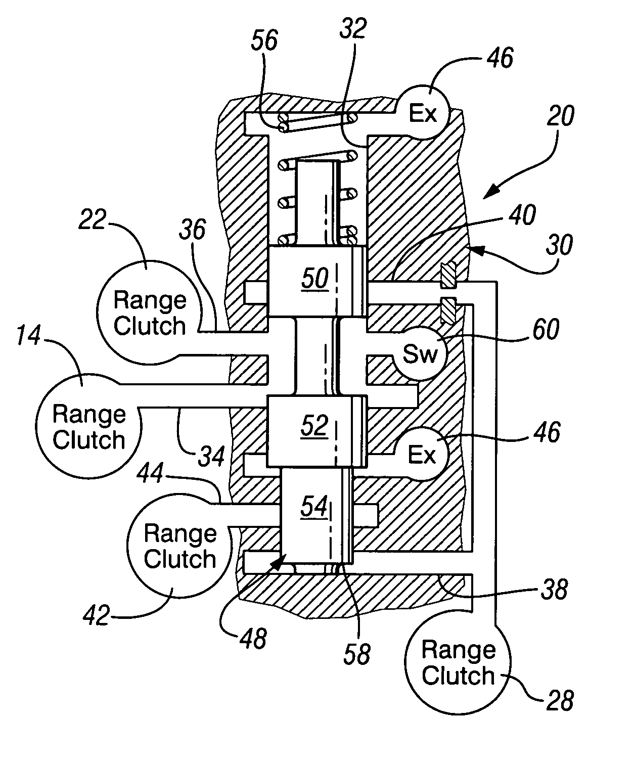
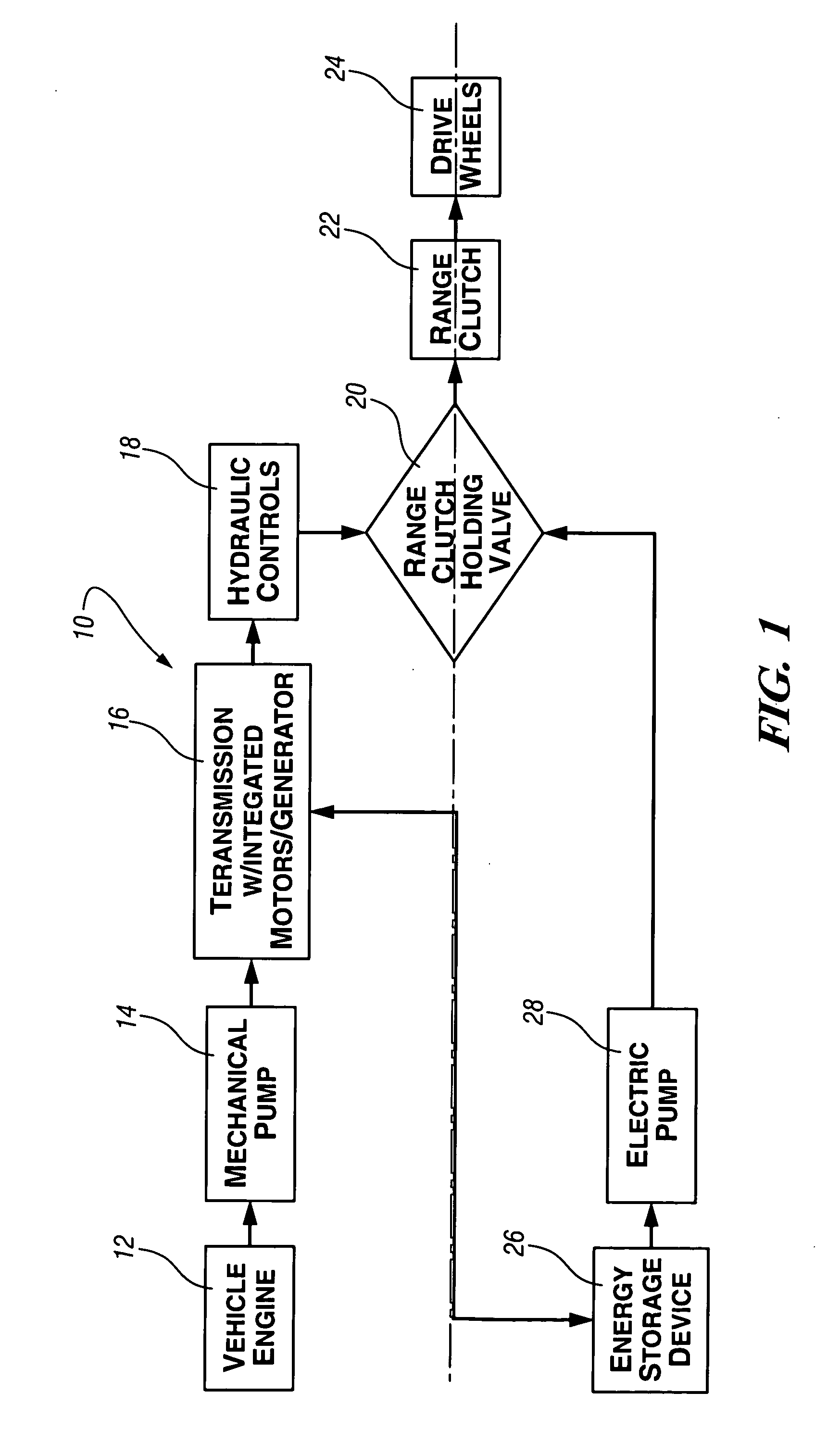
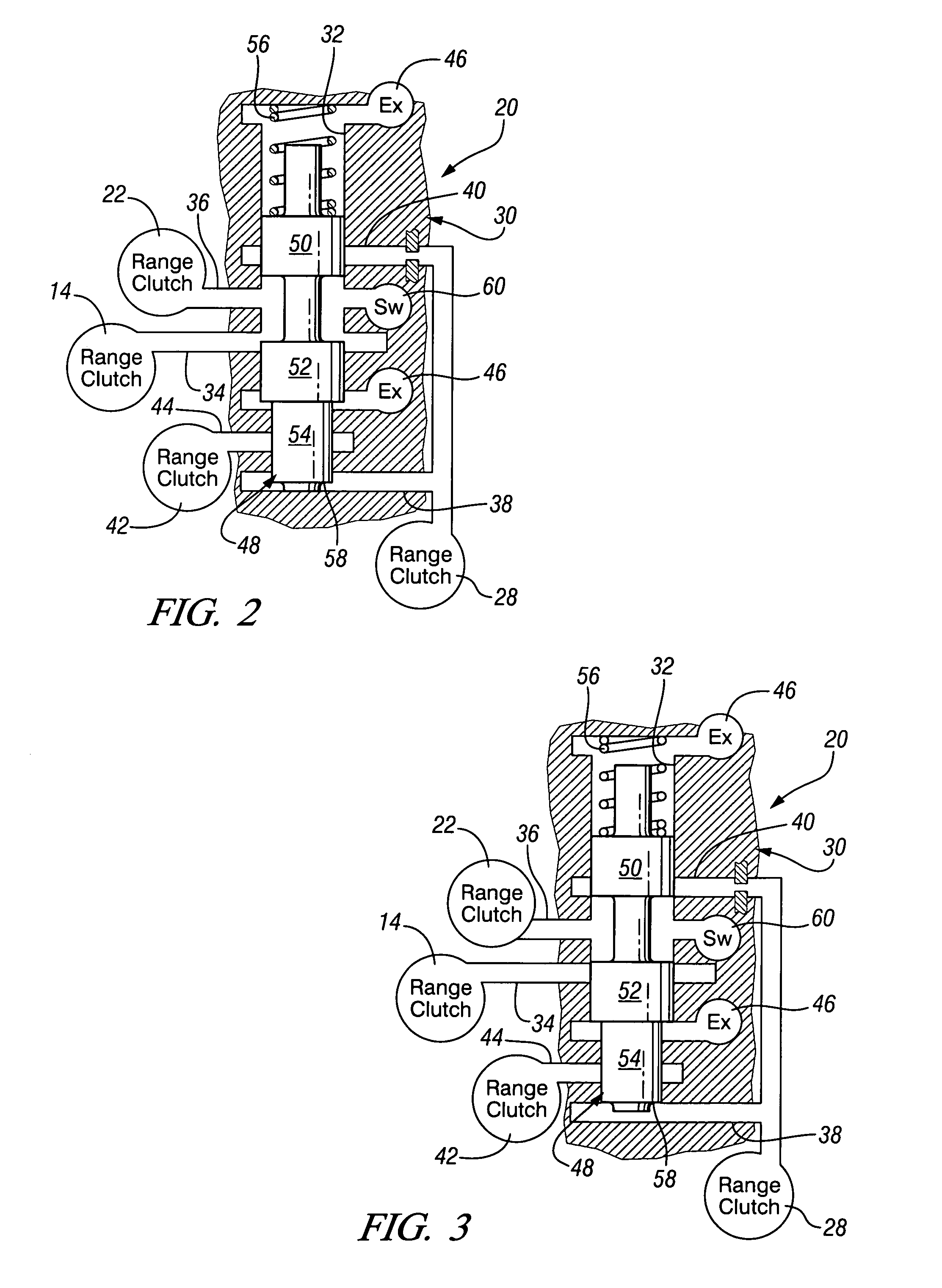
[0021] Referring to the drawings, wherein like characters represent the same or corresponding parts throughout the several views, there is seen in FIG. 1 a schematic representation 10 of a vehicle powertrain. This includes a vehicle engine 12, a mechanical supply pump 14, a hybrid transmission 16 having integrated motor / generators, a hydraulic control system 18, a clutch control valve 20, which may be incorporated within the hydraulic control system 18, a range clutch or torque-transmitting mechanism 22, which is engaged continuously during at least one mode of operation, drive wheels 24, which provide traction drive for the vehicle, energy storage devices 26, and an electric pump 28.

[0022] Both the electric pump 28 and the mechanical pump 14 are well known devices and supply fluid pressure to operate various control functions in their normal operating conditions. The energy storage device 26 is a conventional electrical system, such as batteries. The transmission 16 is conventiona...


PUM


Abstract

A control for parallel hybrid transmission has a valve mechanism, which is operable to supply fluid pressure to a torque-transmitting mechanism with or without the operation of the vehicle engine. The valve mechanism is responsive to an electrically driven pump to supply fluid pressure whenever the engine is discontinued and the electric driven pump is operated.

Description

TECHNICAL FIELD [0001] This invention relates to control valves for power transmissions and, more particularly, to control valves for maintaining at least one torque-transmitting mechanism engaged when the main power plant operation is discontinued. BACKGROUND OF THE INVENTION [0002] Vehicles include an engine, a transmission, and drive wheels. More recently, it has been proposed to use what is known as a hybrid transmission wherein the vehicle powertrain includes an engine, a transmission, and drive wheels with the transmission incorporating one or more electric motors which assist in driving the vehicle or can drive the vehicle while the internal combustion engine is inoperable. [0003] These types of powertrains have the benefit in that they reduce vehicle emissions and improve the overall fuel economy of the vehicle. This is mainly accomplished by allowing the engine to stop or discontinue operations under certain conditions. [0004] In at least one hybrid transmission or powertra...

Claims


Application Information

Patent Timeline
Patent Type & Authority Applications(United States)
IPC IPC(8): B60K6/36B60K6/48G05D7/01G05D16/20
CPCB60K6/36B60K6/48Y02T10/6221F16D48/02F16H2061/0037F16H61/0031F16D2048/0221F16H61/0021Y02T10/62Y10T137/2567Y10T137/86131Y10T137/8671
Inventor LONG, CHARLES F.WEBER, DARREN J.
Owner GM GLOBAL TECH OPERATIONS LLC
Why Eureka
Try Eureka