Elongated coil assembly for electromagnetic borehole surveying

a coil assembly and electromagnetic borehole technology, applied in the direction of surveying, directional drilling, borehole/well accessories, etc., can solve the problems of ineffective technique use, limited range of guidance fields produced by such grids, and ordinary techniques for guiding the drilling of boreholes

Pending Publication Date: 2005-09-29
VECTOR MAGNETICS
View PDF29 Cites 35 Cited by
  • Summary
  • Abstract
  • Description
  • Claims
  • Application Information

AI Technical Summary

Benefits of technology

[0012] The measurements and data generated by the method and apparatus of the invention provides a system for drilling one or more generally horizontal boreholes in closely spaced relationship to a predetermined path.

Problems solved by technology

However, unique problems arise when it becomes necessary to drill such a borehole in an area that is inaccessible, such as beneath a ship's channel in a river, or where multiple boreholes must be drilled parallel to each other with a high degree of accuracy.
In such situations, ordinary techniques for guiding the drilling of boreholes are not always satisfactory.
A major problem with the forgoing technique is the need to drill a large number of boreholes around the circumference of a tunnel while keeping the boreholes accurately spaced and parallel to each other so as to properly define the tunnel along its entire length and with the spacing between adjacent boreholes being substantially constant to ensure that the freezing process will produce a continuous shell around the location where the tunnel is to be excavated.
One approach to solving the problem of drilling spaced, parallel boreholes has involved the use of grids on the surface of the earth for producing magnetic fields to guide the borehole drilling, but if access to the surface above the borehole is not available, this technique cannot be used effectively.
The guidance fields produced by such grids also have a limited range and may not be effective if the borehole being drilled is too deep.
In an urban environment it is often not possible to lay the desired grid on the surface of the earth along the path of the boreholes because of buildings, roads etc.
In addition, the presence of large amounts of steel, which is often present between the surface and the desired tunnel path, severely limits these methods.
This method can work well, though it may suffer from difficulties in making the required ground connection, for the method depends upon a uniform flow of return current in the ground.
Often it is not possible to achieve a uniform flow, and any uncertainty in the return current flow means that highly accurate boreholes cannot be guaranteed.

Method used


Image

  • Elongated coil assembly for electromagnetic borehole surveying
  • Elongated coil assembly for electromagnetic borehole surveying
  • Elongated coil assembly for electromagnetic borehole surveying

Examples


Embodiment Construction

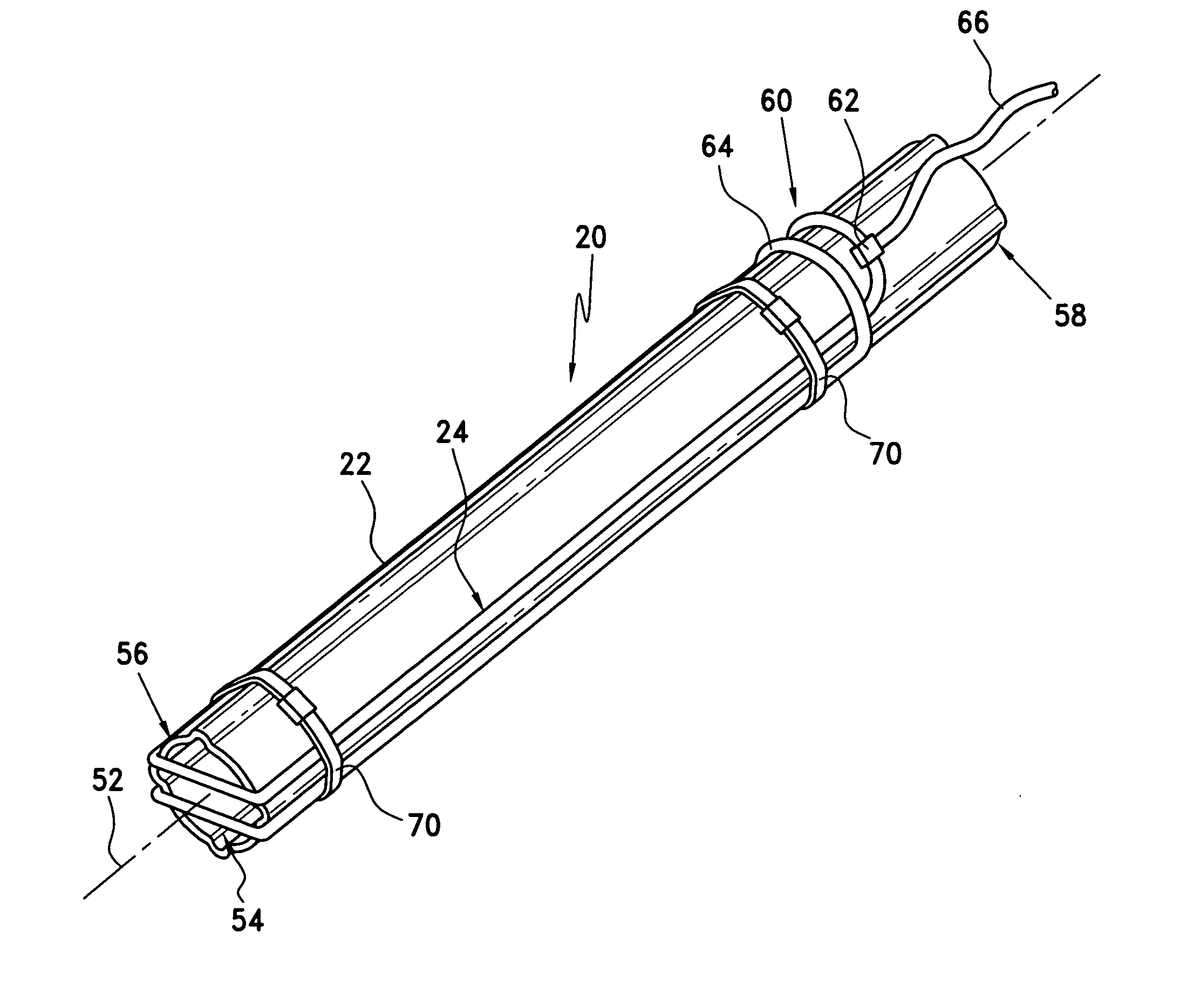
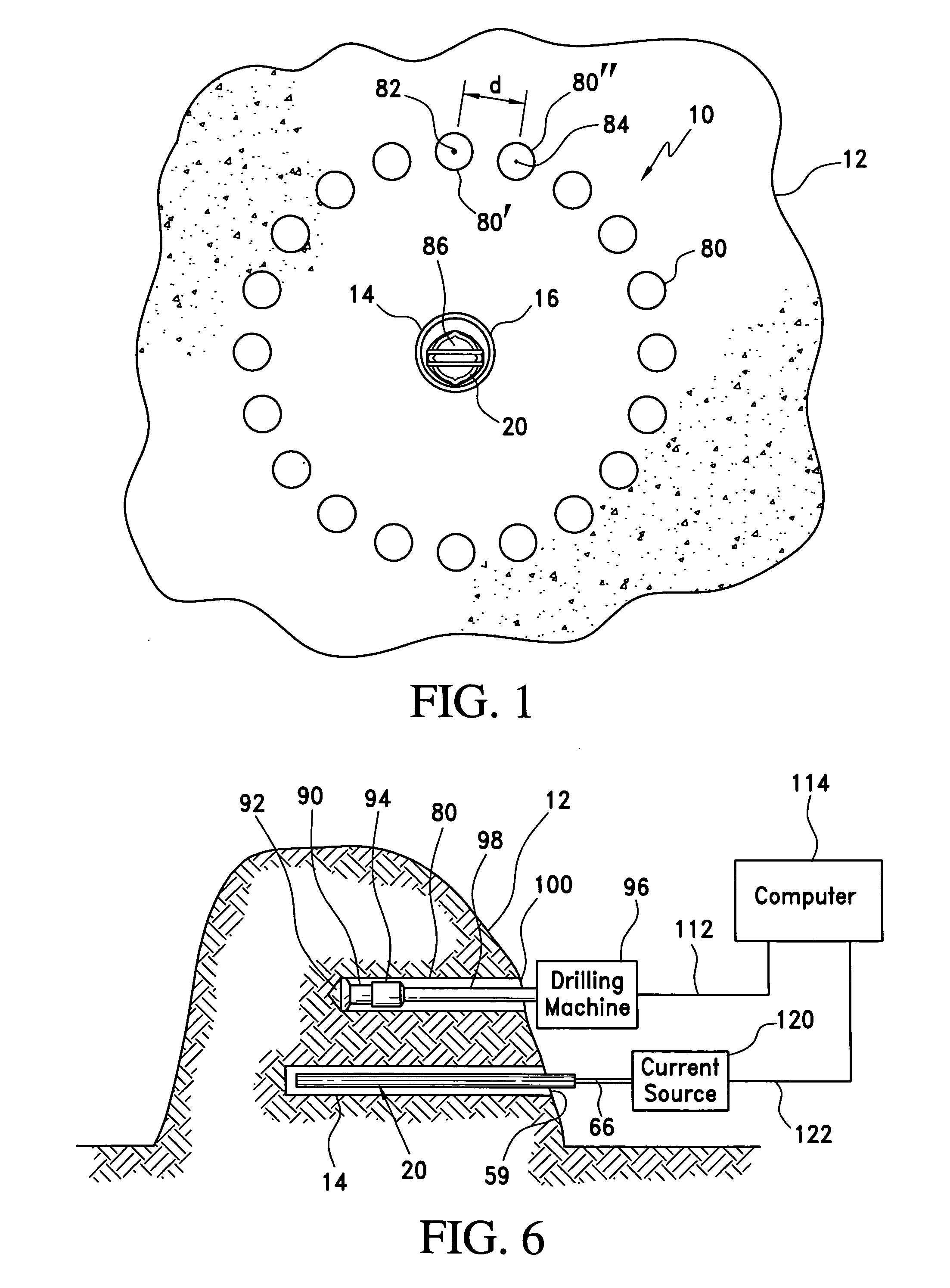
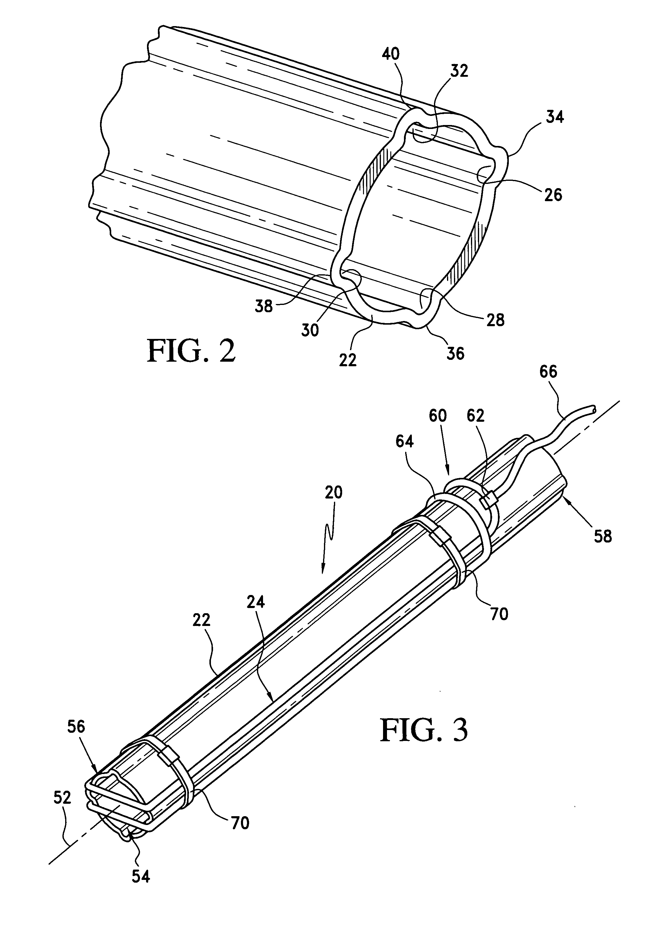
[0024] Turning now to a more detailed description of a preferred embodiment of the present invention, there is illustrated in FIG. 1 a drilling site 10 located in a ground feature 12, such as a hillside, a mountain, or other entryway for one or more generally horizontal boreholes. In the embodiment illustrated in this figure, a plurality of parallel, spaced boreholes defining the circumference of a tunnel to be excavated are illustrated, although it will be understood that the techniques described herein may be used for guiding the drilling of any number of boreholes. In this embodiment, a reference, or guide borehole 14 is first drilled into the earth using known drilling, borehole guidance and logging techniques. The guide borehole may be drilled in a straight line into the side of a mountain, as illustrated in FIG. 6, for example, or may be curved, as when drilling under an obstacle such as a river, lake, or the like, in known manner. The guide borehole preferably is cased with a...


PUM


Abstract

An apparatus and method for surveying the path of a borehole includes three single-axis electromagnetic field sensors and three single axis gravity direction sensors in the borehole being surveyed. A pair of closely spaced, parallel guide wires carrying oppositely directed electric current in a reference borehole generate a known electromagnetic field, which is detected by the sensors. Mathematical analysis of electromagnetic and gravity measurements determines the lateral location and the direction of drilling in the neighboring borehole.

Description

BACKGROUND OF THE INVENTION [0001] This application claims the benefit of U.S. Provisional Application No. 60 / 555,676, filed Mar. 24, 2004, the disclosure of which is hereby incorporated herein by reference.[0002] The present invention relates to a method and apparatus for drilling generally horizontal boreholes, and more particularly to a guidance system for drilling such boreholes to a close tolerance along a specified path. [0003] The technology for drilling boreholes into or through hills or mountains, under rivers, and the like has been well developed over the years. However, unique problems arise when it becomes necessary to drill such a borehole in an area that is inaccessible, such as beneath a ship's channel in a river, or where multiple boreholes must be drilled parallel to each other with a high degree of accuracy. In such situations, ordinary techniques for guiding the drilling of boreholes are not always satisfactory. [0004] An example of the need for a high degree of a...

Claims


Application Information

Patent Timeline
Patent Type & Authority Applications(United States)
IPC IPC(8): E21B7/04E21B47/02E21B47/022E21B47/024E21D9/00E21D9/04
CPCE21B47/02216E21D9/04E21D9/003E21B47/024E21B47/0228
Inventor KUCKES, ARTHUR F.TEER, JOHN
Owner VECTOR MAGNETICS
Why Eureka
Try Eureka