
Rotary cutting bit having spark suppression sleeve

a technology of spark suppression and cutting bit, which is applied in the field of cutting tools, can solve the problems of fire or explosion, spark production between, etc., and achieve the effects of reducing the contact area between the shank and the composite sleeve, reducing the likelihood of the sleeve failing, and being tougher or stronger

Inactive Publication Date: 2005-09-29
SANDVIK INTELLECTUAL PROPERTY AB
View PDF8 Cites 47 Cited by
  • Summary
  • Abstract
  • Description
  • Claims
  • Application Information

AI Technical Summary

Benefits of technology

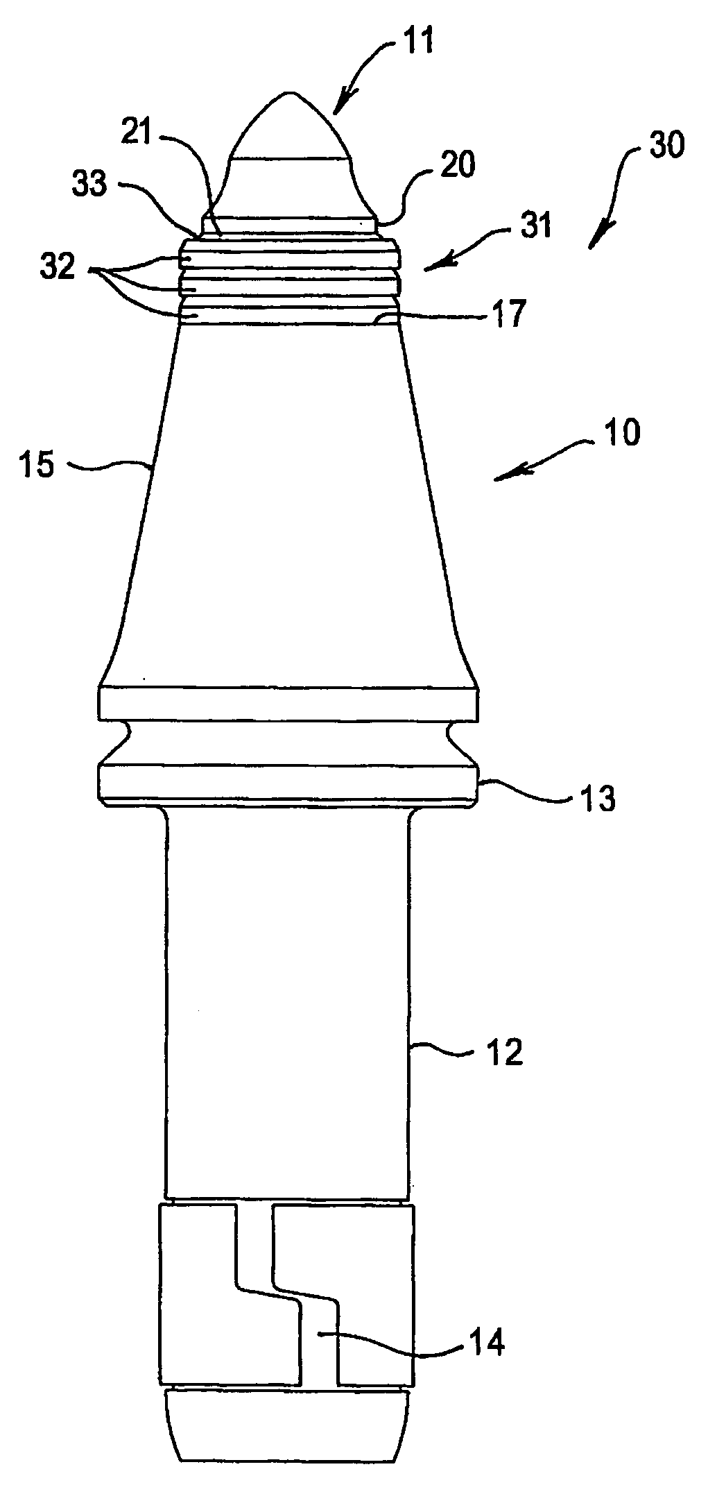
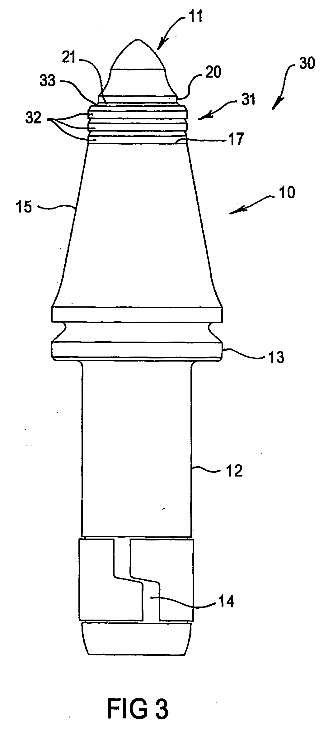
[0010] By the attachment of the sleeve about the shank, the portion of the shank in the immediate vicinity of the cutting tip, which typically is the most likely to contact either the earth face being cut, or the fragments of earth being dislodged from the face, and to therefore generate an incendive spark, is shielded against that contact by the spark resistant material. The propensity for spark production is therefore reduced.
[0015] In a typical size of cutting pick, the axial height of the sleeve could be in the region of about 10 mm to 15 mm, with the radial thickness of the sleeve between inner and outer diameter, about 3 mm to 5 mm. Production of a sleeve in these dimensions in tungsten carbide may present certain difficulties and therefore it is preferable that the sleeve be produced in sleeve portions or rings of reduced height, such as about 4 mm in axial height. These portions can then be attached to the shank to form a composite sleeve of the required height. In the preferred arrangement, three sleeve portions are employed, although two sleeve portions, or four or more, may be employed as required. In a preferred arrangement, each sleeve portion has the same inside and outside diameters, and preferably the inner and outer surfaces are parallel, although the outer surface can include a chamfered edge or edges to reduce the likelihood of sharp edge breakage.
[0016] The envisaged difficulty with a sleeve formed of one piece relates principally to the difference in the coefficient of expansion between the sleeve and the shank when the sleeve is attached to the shank. If the shank material is steel and the sleeve is tungsten carbide, the shank will expand and shrink as the steel is heated and the shank will thereafter shrink while the steel cool cools at a rate which is about twice as fast as that of the sleeve. The difference in rate of shrinking can introduce stresses in the sleeve, which typically will be more brittle than the shank and if the stresses are sufficient, the sleeve cart crack. If a plurality of shank portions in the form of rings are employed, then the contact area between the shank and the composite sleeve can be reduced by breaks between the rings. This is because the medium employed to fix the rings to the shank extends between the rings and the shank and between the rings themselves. That medium, which is, as later described, preferably braze, can absorb some of the induced stresses and therefore reduce the likelihood of the sleeve failing. This has the additional benefit that the composite sleeve can be tougher or stronger than a single-piece sleeve, so that the likelihood of wear or failure under operating loads is also reduced.
[0017] In a preferred form of a cutting pick according to the invention, the shank defines a shoulder between a generally conical section and cylindrical section. The conical section converges towards the cylindrical section, while the cylindrical section defines a recess for receipt of a base portion of the cutting tip. That receipt can constitute either an insert or cap style cutting pick. In this arrangement, the sleeve is attached to the shank about the cylindrical portion and is supported against the shoulder. Advantageously, this arrangement provides for accurate location of the sleeve on the shank and provides a surface against which the sleeve can react impact loads during a cutting operation.
[0018] A shank of the above kind can define a second shoulder, which is axially spaced from the first shoulder in a direction away from the cutting tip, and in this arrangement, a second sleeve can be attached about the shank to extend between the first and second shoulders. In this manner, a further portion of the shank can be protected against contact with the earth face and so further lessen the risk of incendive spark production.
[0023] It will be appreciated that the above discussion principally concerns the reduction or elimination of incendive spark production, during engagement of a cutting pick with an earth face. While that result is the primary achievement of the invention, a secondary aspect of the invention, is to provide the shank with a resistance to wear. Shanks formed from steel, readily wear over time, and it is often the case that the steel shank wears more quickly than the harder cutting tip, so that the cutting pick must be replaced earlier than desirable i.e. before the cutting pick is sufficiently worn. In other words, wear of the shank can reduce the effective life of the cutting pick. Pick wear often occurs principally in the vicinity of the shank immediately adjacent the cutting tip. Accordingly, by suitable selection of sleeve material, the steel shank in that vicinity can be shielded against engagement with earth face or fragments, that would otherwise cause it to wear and therefore the life of the cutting pick can be improved. The selection of a sleeve material that is the same or effectively equivalent to the material of the cutting tip, can provide useful wear resistance for this purpose.

Problems solved by technology

Disadvantageously, the equipment used in coal mining can generate incendive sparks and thus cause fires or explosion.
This highly aggressive engagement between the picks and the earth face can result in spark production between them.

Method used


Image

  • Rotary cutting bit having spark suppression sleeve
  • Rotary cutting bit having spark suppression sleeve
  • Rotary cutting bit having spark suppression sleeve

Examples


Embodiment Construction

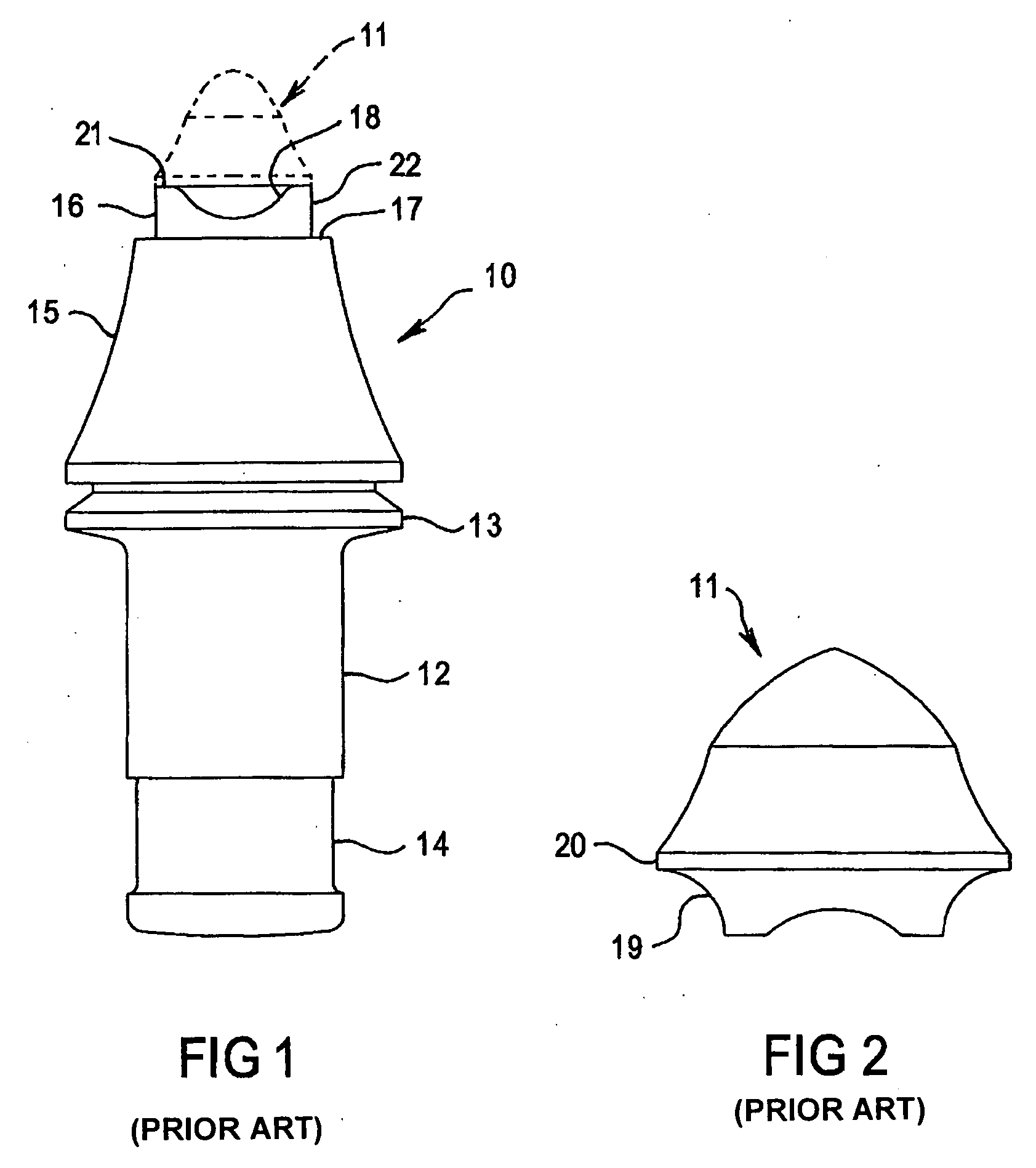
[0029]FIGS. 1 and 2 respectively show a shank 10 of a cutting pick, and a tungsten carbide tip 11 which is shaped for attachment to the shank 10. The shank 10 includes a body section 12, which includes a flange 13 at one end and a recess 14 remote from the flange 13, and whereby the flange 13 and the recess 14 cooperate with a rotary cutting drum for fixing of the cutting pick to the drum. The manner with which the shank 10 is fixed to the drum will be known to a person skilled in the art and therefore will not be further described or illustrated herein.

[0030] The shank 10 further defines a substantially conical portion 15, a cylindrical portion 16 and a shoulder 17. It will be appreciated that the shoulder 17 is defined by a reduction in the diameter of the conical portion 15 immediately adjacent the cylindrical portion 16.

[0031] The cylindrical portion 16 includes a recess 18 for receiving a base portion of a cutting tip, such as of the kind shown in FIG. 2. Referring to that fi...


PUM


Abstract

A cutting pick includes an elongate shank, a cutting tip fixed to one end of the shank to project from that end and which is of a material that is harder than the material of the shank, and an annular sleeve which is attached about the shank adjacent the cutting tip. The sleeve is of a material (e.g., tungsten carbide) which is harder than the material of the shank and which has a lower propensity for incendive spark production during a cutting operation than the material of the shank. The sleeve includes a plurality of annular sleeve portions which are attached about the shank immediately adjacent to each other.

Description

[0001] This application claims priority under 35 U.S.C. § 119 and / or 365 to Patent Application Serial No. 2004.201284 filed in Australia on Mar. 26, 2004, the entire content of which is hereby incorporated by reference. BACKGROUND OF THE INVENTION [0002] The present invention relates to cutting tools used for mining and excavation purposes. The present invention has been developed principally for use in the mining of coal and in that use, typically underground coal mining. It will therefore be convenient to describe the invention in relation to that use although it will be readily appreciated that the invention could be employed for any mining or excavation operation to which its function is suitable. [0003] Various different forms of equipment and machinery can be employed for mining and excavation operations, and typically it is the type of mining or excavation taking place, and the type of earth being mined or excavated, that dictates the type of equipment and machinery that is a...

Claims


Application Information

Patent Timeline
Patent Type & Authority Applications(United States)
IPC IPC(8): E21C25/14E21C35/183E21C35/197E21F5/00
CPCE21F5/00E21C35/197
Inventor SLEEP, KEITHWEAVER, STEVEN
Owner SANDVIK INTELLECTUAL PROPERTY AB
Learn More