Magnetic circuits of electrical machines

Inactive Publication Date: 2005-09-29
SWITCHED RELUCTANCE DRIVES
View PDF16 Cites 17 Cited by
  • Summary
  • Abstract
  • Description
  • Claims
  • Application Information

AI Technical Summary

Benefits of technology

[0026] In a further embodiment the invention includes a method of increasing the flux carrying capacity of an electrical machine which comprises a stator made of laminations of magnetizable material of a first thickness, and a rotor made of laminations of magnetizable material of a second thickness, the method comprising: arranging at least one

Problems solved by technology

Usually only machines with unvarying flux have unlaminated structures.
Of course, the decreasing lamination thickness brings many disadvantages, not least in terms of cost of material and of manufacturing difficulty.
Inspection of the curves of FIG. 4, however, shows that this results in a non-linear increase in the mmf, resulting in a non-linear increase in the resistive losses of the machine and therefore in the thermal management problems associated with cooling.
There is likely to be a consequential increase in

Method used


Image

  • Magnetic circuits of electrical machines
  • Magnetic circuits of electrical machines
  • Magnetic circuits of electrical machines

Examples


Embodiment Construction

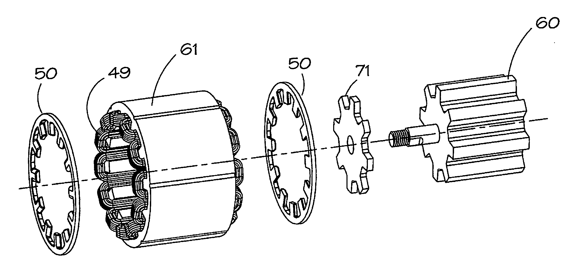
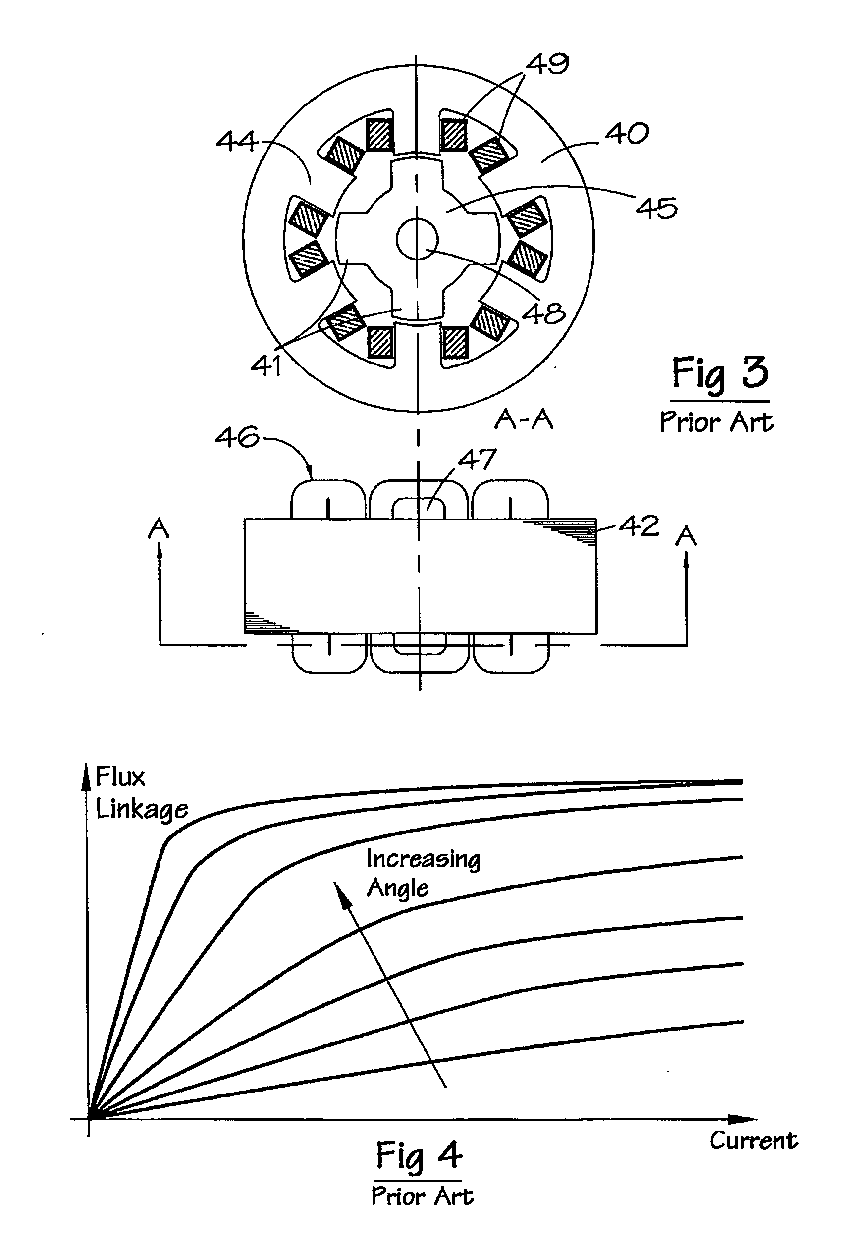
[0040]FIG. 5 shows a stator flux plate which is shaped to co-operate with the end of a stator core pack having a stator back-iron portion, and poles having pole sides and pole ends, as shown in FIG. 3, for example. A solid flux plate 50 has an annular portion 51, whose inside and outside diameters correspond to the back-iron portion of the stator lamination. A number of teeth 52 project radially inwardly from the annular portion. Each tooth 52 has dimensions which allow the tooth to match the shape of the stator poles 44, or to lie slightly inside the profile of the pole. The number of teeth on the flux plate is the same as the number of stator poles. The cross section of the plate shows it has a flat side 53 which lies adjacent the end face of the stack of magnetizable laminations making up the stator core 42. The opposite side 54 of the plate is profiled at the teeth to match the profile of the gap 47 (see FIG. 3) created between the coil overhang 46 and the pole end. FIG. 5 shows...


PUM


Abstract

An electrical machine is provided with one or more flux plates at the end of the stator and rotor cores. On the stator side, the plate is profiled to substantially fill the void between the core and the winding. The plates are ferromagnetic and form part of the main magnetic circuit. They carry maximum flux at zero and low switching frequencies and substantially no flux at the highest operating speeds.

Description

CROSS-REFERENCE TO RELATED APPLICATION [0001] The subject matter of this application is related to the subject matter of British Patent Application No. GB 0403395.7, filed Feb. 16, 2004, priority to which is claimed under 35 U.S.C. § 119 and which is incorporated herein by reference. BACKGROUND OF THE INVENTION [0002] 1. Field of the Invention [0003] This invention relates to improvements in the magnetic circuits of electrical machines. It is particularly suitable for those machines with salient poles, for example, switched reluctance machines. [0004] 2. Description of Related Art [0005] The control and operation of switched reluctance machines generally are described in the paper “The Characteristics, Design and Applications of Switched Reluctance Motors and Drives” by J. M. Stephenson and R. J. Blake delivered at the PCIM'93 Conference and Exhibition held in Nurnberg, Germany, 21-24 Jun. 1993, which is incorporated herein by reference. In that paper the “chopping” and “single-puls...

Claims


Application Information

Patent Timeline
IPC IPC(8): H02K1/12H02K1/14H02K3/34H02K1/18H02K16/00H02K17/00H02K19/10H02K19/24H02K29/00
CPCH02K19/103H02K1/146H02K3/18
Inventor MCCLELLAND, MICHAEL LEO
Owner SWITCHED RELUCTANCE DRIVES
Why Eureka
Try Eureka