
Wireless communications device having type-II all-digital phase-locked loop (PLL)

a communication device and phase-locked loop technology, applied in the field of digital typeii (and), can solve the problems of slow signal acquisition and settling, phase error offset, etc., and achieve the effect of fast signal acquisition and rapid settl

Active Publication Date: 2005-09-29
TEXAS INSTR INC
View PDF7 Cites 2 Cited by
  • Summary
  • Abstract
  • Description
  • Claims
  • Application Information

AI Technical Summary

Benefits of technology

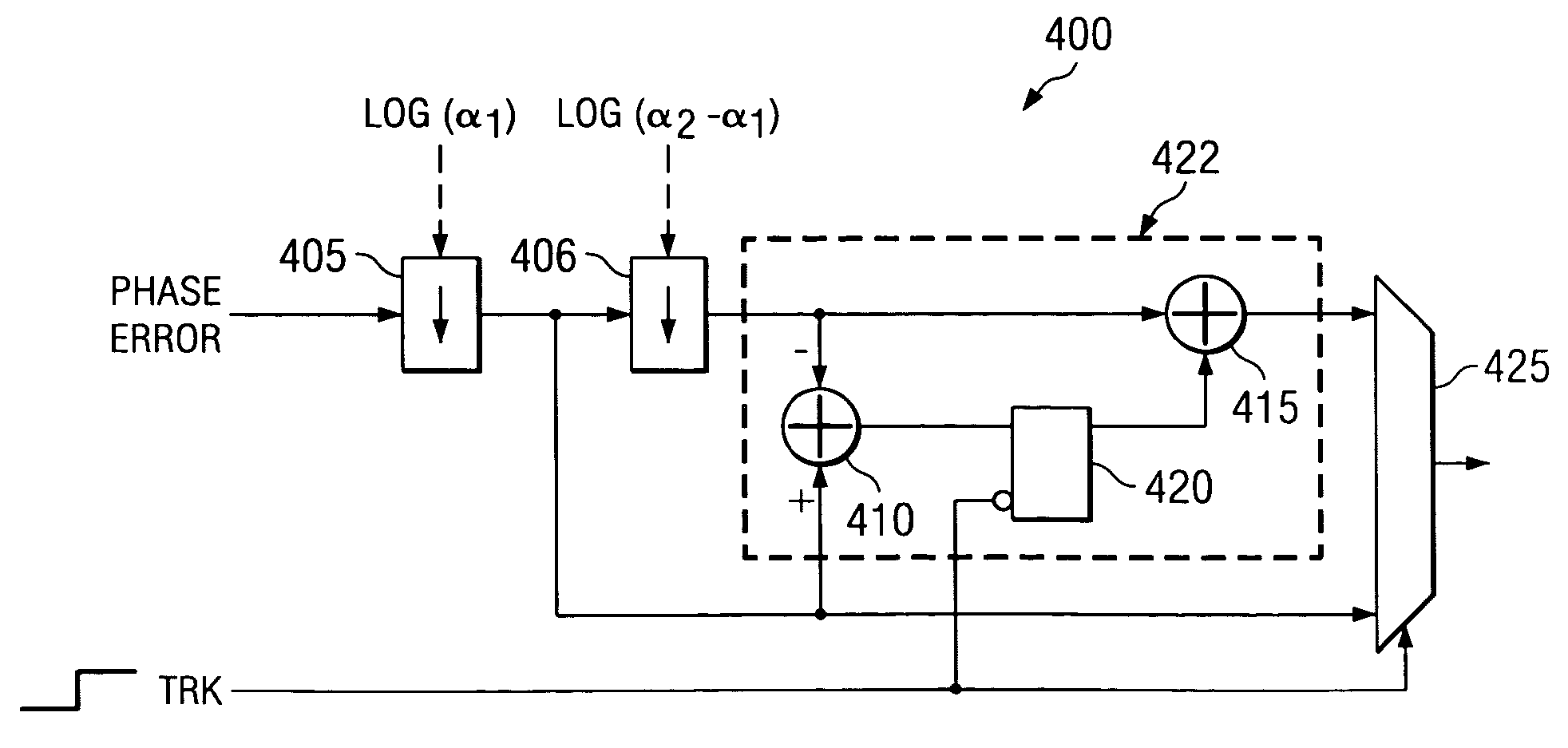
[0011] In accordance with a preferred embodiment of the present invention, a method for improving signal acquisition performance in a phase-locked loop (PLL) comprising acquiring a signal using a proportional loop gain circuit, measuring an offset in the signal, activating an integral block to accumulate an adjusted signal, and combining outputs from the proportional loop gain circuit and the integral accumulator to produce an oscillator tuning signal.
[0015] An advantage of a preferred embodiment of the present invention is that through the use of a type-I PLL in an initial signal acquisition mode and then a type-II PLL in signal tracking mode, fast signal acquisition can be combined with higher order signal and noise filtering.
[0016] Another advantage of a preferred embodiment of the present invention is that ability to eliminate the offset (residue) introduced by the type-I operation can help the type-II PLL in signal tracking mode settle more rapidly. The removal of the offset (residue) requires minimal additional hardware and the offset can optionally be retained and permitted to settle naturally, using the PLL.

Problems solved by technology

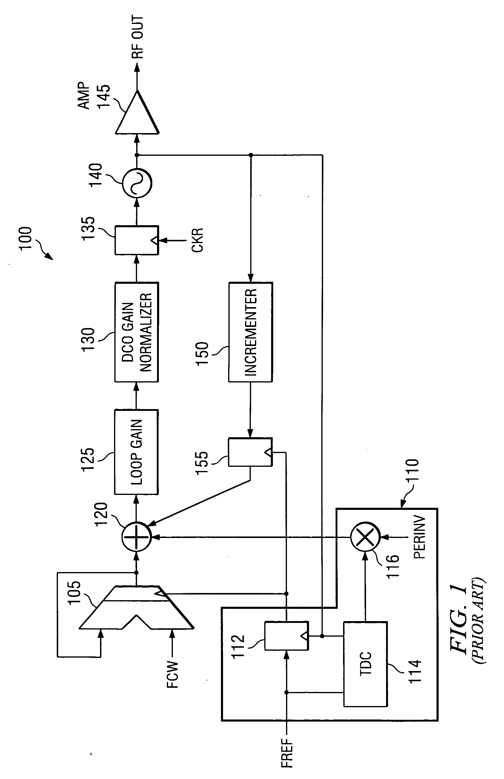
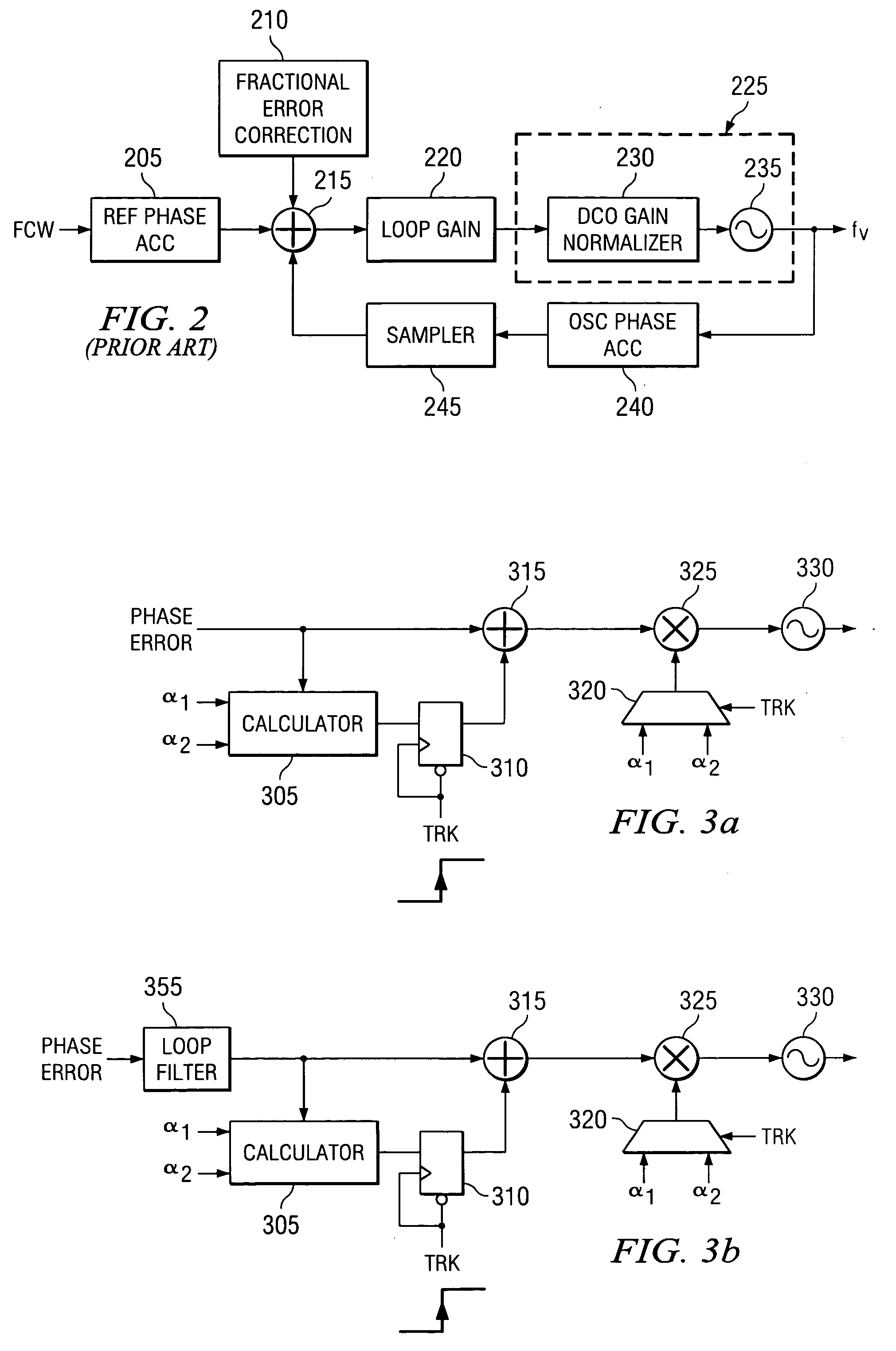
One disadvantage of the prior art is that the use of a type-II PLL may result in slow signal acquisition and settling.
A second disadvantage of the prior art is that an offset is present in the phase error from the use of the type-I PLL in the initial signal acquisition mode.

Method used


Image

  • Wireless communications device having type-II all-digital phase-locked loop (PLL)
  • Wireless communications device having type-II all-digital phase-locked loop (PLL)
  • Wireless communications device having type-II all-digital phase-locked loop (PLL)

Examples


Embodiment Construction

[0037] The making and using of the presently preferred embodiments are discussed in detail below. It should be appreciated, however, that the present invention provides many applicable inventive concepts that can be embodied in a wide variety of specific contexts. The specific embodiments discussed are merely illustrative of specific ways to make and use the invention, and do not limit the scope of the invention.

[0038] The present invention will be described with respect to preferred embodiments in a specific context, namely an all-digital phase-locked loop synthesizer for use in a Bluetooth compliant wireless device. The invention may also be applied, however, to other applications wherein an all-digital phased-lock loop synthesizer may be used, such as in wired and wireless devices where rapid signal acquisition may be required while at the same time, a higher order of noise filtering is desired.

[0039] With reference now to FIG. 1, there is shown a block diagram illustrating a p...


PUM


Abstract

System and method for providing type-II (and higher order) phase-locked loops (PLLs) with a fast signal acquisition mode. A preferred embodiment comprises a wireless communication device having a loop filter with a proportional loop gain path (proportional loop gain circuit 1115) and an integral loop gain block (integral loop gain block 1120). The proportional loop gain path is used during signal acquisition to provide large loop bandwidth, hence fast signal acquisition of a desired signal. Then, during the PLL's signal tracking phase, the integral loop gain block is enabled and its output is combined with output from the proportional loop gain path to provide higher order filtering of the desired signal. An offset that may be present due to the use of the proportional loop gain path can be measured and subtracted to help improve signal tracking settling times.

Description

[0001] This application claims the benefit of U.S. Provisional Applications No. 60 / 389,872, filed on Jun. 19, 2002, entitled “Graduated Exponential Bandwidth Shifting of an All-Digital PLL”, No. 60 / 441,080, filed on Jan. 17, 2003, entitled “Type-II-All-Digital PLL in Deep-Submicron CMOS”, which application is hereby incorporated herein by reference. CROSS-REFERENCE TO RELATED APPLICATIONS [0002] This application is related to the following co-pending and commonly assigned patent applications: Ser. No. 09 / 728,180, filed Dec. 1, 2000, entitled “Digital PLL with Gear Shift”; Serial No.______, filed Jun. 19, 2003, entitled “Fine-Grained Gear-Shifting of a Digital Phase-Locked Loop (PLL)” which application is hereby incorporated herein by reference.TECHNICAL FIELD [0003] The present invention relates generally to phased-locked loop (PLL) circuits, and more particularly to digital type-II (and higher order) PLLs desiring a fast signal acquisition mode. BACKGROUND [0004] An all digital pha...

Claims


Application Information

Patent Timeline
IPC IPC(8): H03F1/02H03F1/32H03L7/093H03L7/099H03L7/107
CPCH03L7/093H03L7/0991H03L7/107H03F1/3282H03L2207/50H03F1/0211H03L7/1075
Inventor STASZEWSKI, ROBERT B.LEIPOLD, DIRKMUHAMMAD, KHURRAM
Owner TEXAS INSTR INC
Learn More