Reflective liquid crystal display device and liquid crystal display unit

a liquid crystal display and liquid crystal technology, applied in non-linear optics, instruments, optics, etc., can solve the problems of long-term reliability decline, electrode corrosion is a big issue, and the coating of the electrode surface 143/b> with protective film is not enough, so as to achieve high moisture resistance, prevent electrode corrosion, and secure moisture resistance

Active Publication Date: 2005-09-29
SONY CORP
View PDF4 Cites 13 Cited by
  • Summary
  • Abstract
  • Description
  • Claims
  • Application Information

AI Technical Summary

Benefits of technology

[0013] However, in the reflective liquid crystal display device, when the inorganic protective film 147 is used in the pixel region 101, the inorganic protective film 147 becomes a capacity component between the transparent electrode 132 and the reflective pixel electrode 143, thereby an electric field applied to the liquid crystal 150 is reduced. In particular, in the case where a liquid crystal layer is thin, for example, approximately 3 μm or less, the effect will be increased. When the pixel region 101 is not coated with the inorganic protective film 147, and the inorganic protective film 147 is formed only in the peripheral region 102 in order to prevent the effect, there is no protective film on the reflective pixel electrode 143, so when the reflective pixel electrode 143 is exposed to air in a manufacturing process after forming the reflective pixel electrode 143, the surface of the reflective pixel electrode 143 is oxidized, thereby the reflectivity of the reflective pixel electrode 143 declines. Moreover, coating the surface of the electrode 143 with the protective film is not enough, because moisture may enter from an end portion 201 around the substrate.
[0027] In particular, as the liquid crystal display unit according to an embodiment of the invention displays an image through using the reflective liquid crystal display device according to an embodiment of the invention, an image can be displayed for a long term in good condition.

Problems solved by technology

In particular, in the reflective liquid crystal display device, an aluminum-based metal material which is generally used in an LSI (Large Scale Integrated circuit) is used as the reflective pixel electrode 143, so the electrode 143 is corroded by atmospheric moisture under such a high temperature, and long-term reliability of the device declines.
In addition, the transparent electrode 132 is generally made of ITO (Indium Tin Oxide), so the electrode corrosion is a big issue in the pixel electrode substrate 140.
Moreover, in the transmissive liquid crystal display device, ITO is generally used in the pixel electrode substrate, so the corrosion is an issue specific to the reflective liquid crystal display device using the reflective pixel electrode 143 made of a metal material.
Moreover, coating the surface of the electrode 143 with the protective film is not enough, because moisture may enter from an end portion 201 around the substrate.

Method used


Image

  • Reflective liquid crystal display device and liquid crystal display unit
  • Reflective liquid crystal display device and liquid crystal display unit
  • Reflective liquid crystal display device and liquid crystal display unit

Examples


first embodiment

[0046]FIG. 8 shows the whole structure of a reflective liquid crystal display device according to a first embodiment of the invention. FIG. 9 shows a plan view of the reflective liquid crystal display device. FIG. 8 corresponds to a sectional view taken along a line A-A of FIG. 9. The reflective liquid crystal display device includes a pair of a transparent electrode substrate 30 and a pixel electrode substrate 40 which face each other and a liquid crystal 50 injected between the substrates 30 and 40. In FIG. 9, the transparent electrode substrate 30 is not shown. The transparent electrode substrate 30 and the pixel electrode substrate 40 are bonded together with a predetermined spacing therebetween by a seal portion 51. As the liquid crystal 50, for example, a vertically aligned liquid crystal can be used.

[0047] The transparent electrode substrate 30 includes a glass substrate 31, and a transparent electrode 32 which are laminated on a surface of the glass substrate 31 in contact ...

second embodiment

[0071] A second embodiment relates to a moisture resistant structure in the case where a terminal (common electrode) for supplying powder to the transparent electrode 32 is disposed on a pixel electrode substrate side. In the following description, like components are denoted by like numerals as of the first embodiment and will not be further described.

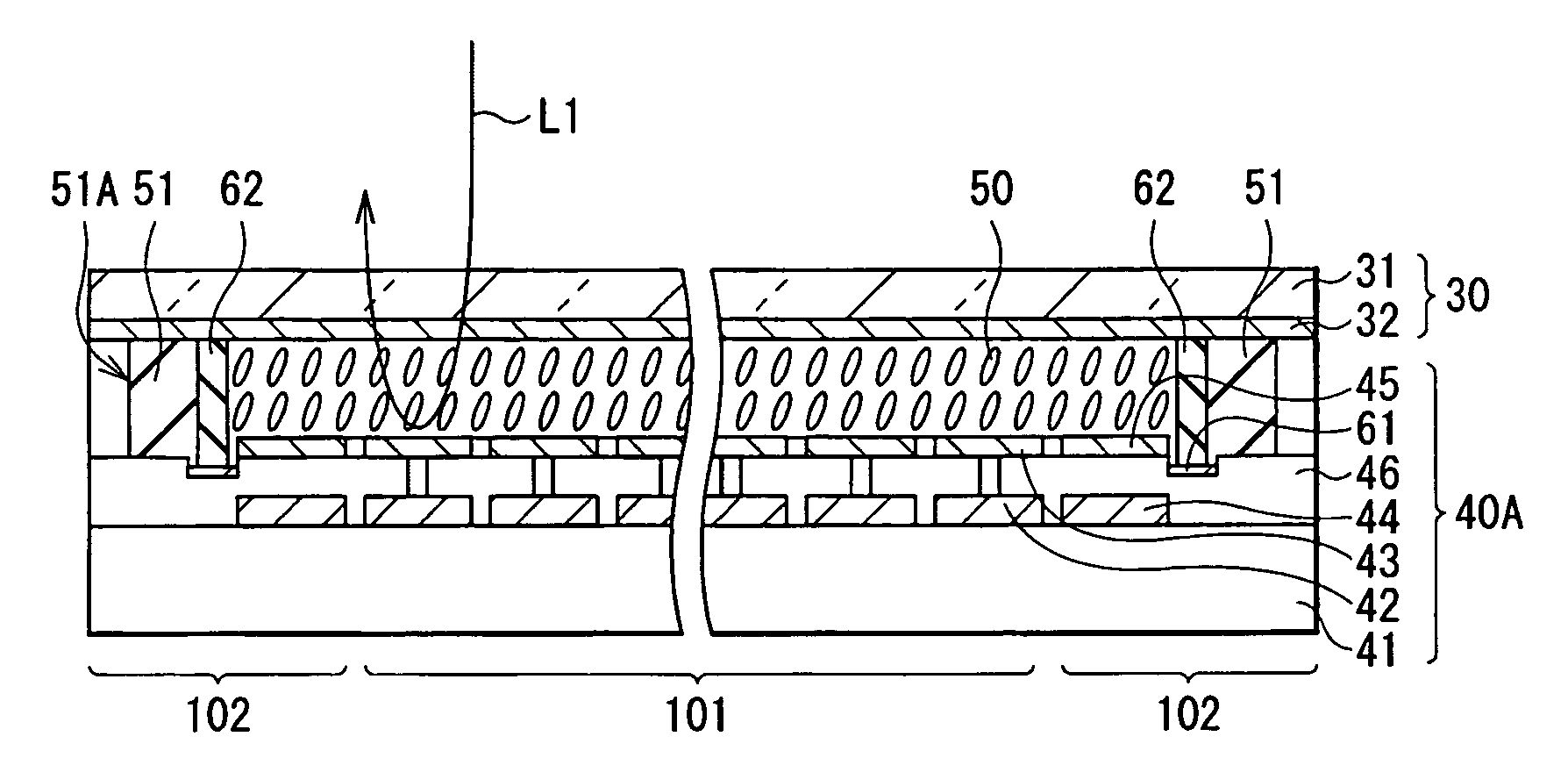
[0072]FIG. 13 shows the whole structure of a reflective liquid crystal display device according to the embodiment. FIG. 14A shows a plan view of the reflective liquid crystal display device. FIG. 13 corresponds to a sectional view taken along a line A-A of FIG. 14A. In FIG. 14A, the transparent electrode substrate 30 is not shown. The reflective liquid crystal display device comprises a pixel electrode substrate 40A including a common electrode 61. FIG. 14B shows an enlarged view of a common electrode 61. In the embodiment, “light-shielding electrode 45” and “common electrode 61” correspond to specific examples of “metal film” in the...

first embodiment and second embodiment

Modifications of First Embodiment and Second Embodiment

[0076] Modification of the first embodiment and the second embodiment relate to a moisture-resistant structure of a reflective liquid crystal display device including a liquid crystal inlet. In the following description, like components are denoted by like numerals as of the first embodiment and the second embodiment, and will not be further described.

[0077]FIG. 15 shows a modification of the reflective liquid crystal display device according to the first embodiment. In the reflective liquid crystal display device, a liquid crystal inlet 52 is disposed in a part of the seal portion 51, and the liquid crystal 50 is injected through the liquid crystal inlet 52. After that, the liquid crystal inlet 52 is sealed with a seal compound 53. The position where the liquid crystal inlet 52 is disposed is not limited to a position shown in FIG. 15. Moreover, a plurality of liquid crystal inlets 52 may be disposed. In the reflective liquid ...


PUM

PropertyMeasurementUnit
thicknessaaaaaaaaaa
transparentaaaaaaaaaa
voltageaaaaaaaaaa

Abstract

A reflective liquid crystal display device and a liquid crystal display unit capable of achieving high moisture resistance and securing long-term reliability through specifically preventing electrode corrosion in a surface portion of a pixel electrode substrate are provided. A seal portion bonds a pixel electrode substrate and a transparent electrode substrate together with a predetermined spacing in between. In this case, the pixel electrodes and a metal film are formed inside an outer surface of the seal portion on the pixel electrode substrate. Thereby, the pixel electrodes and the metal film are not exposed to air, and the moisture resistance can be secured, and electrode corrosion can be prevented. Moreover, as an adhesive surface of the seal portion is a substrate surface, compared to the case where peripheral end sources of the whole device are coated, sufficient adhesion can be secured for a long term.

Description

CROSS REFERENCES TO RELATED APPLICATIONS [0001] The present invention contains subject matter related to Japanese Patent Application JP 2004-081297 filed in the Japanese Patent Office on Mar. 23, 2004, the entire contents of which being incorporated herein by reference. BACKGROUND OF THE INVENTION [0002] 1. Field of the Invention [0003] The present invention relates to a reflective liquid crystal display device which comprises a reflective pixel electrode, and a liquid crystal display unit which displays an image through the use of the reflective liquid crystal display device such as a reflective liquid crystal projector. [0004] 2. Description of the Related Art [0005] In recent years, improvements in definition, downsizing and contrast of projection displays have been rapidly progressed, thereby demands for display devices used for the projection displays have been increased. However, transmissive liquid crystal display devices which are mainly used at present cannot meet the deman...

Claims


Application Information

Patent Timeline
Patent Type & Authority Applications(United States)
IPC IPC(8): G02F1/1333G02F1/13G02F1/1335G02F1/1339G02F1/1343
CPCG02F1/133509G02F1/133553G02F2201/50G02F1/136277G02F2001/133388G02F1/1339G02F1/133388
Inventor AKIMOTO, OSAMU
Owner SONY CORP
Why Eureka
Try Eureka