Variable square-wave drive device

a drive device and variable square wave technology, applied in the direction of coupling device connection, camera focusing arrangement, printers, etc., can solve the problem of inability to carry out a focus control function

Inactive Publication Date: 2005-09-29
SAMSUNG ELECTRO MECHANICS CO LTD
View PDF16 Cites 19 Cited by
  • Summary
  • Abstract
  • Description
  • Claims
  • Application Information

AI Technical Summary

Benefits of technology

[0014] Therefore, the present invention has been made in view of the above problems, and it is an object of the invention to provide a variable square-wave drive device for controlling square waves using a feedback- or bias-control method to vary the square waves, such that it can correctly control a curvature of an LL (Liquid Lens), and can more precisely and stably control focus and zoom functions of a camera module.
[0017] Preferably, the power-supply unit may be powered on or off by an input power-saving signal to reduce power consumption.
[0019] Preferably, the switching controller may be synchronized with the clock signal of the frequency-divider / duty controller, so that it can be more correctly performed.

Problems solved by technology

However, the aforementioned conventional liquid crystal lens drive circuit cannot control a curvature of the LL, such that it is also unable to perform a focus control function capable of being carried out using such a curvature control function.

Method used


Image

  • Variable square-wave drive device
  • Variable square-wave drive device
  • Variable square-wave drive device

Examples


Embodiment Construction

[0032] Now, preferred embodiments of the present invention will be described in detail with reference to the annexed drawings. In the drawings, the same or similar elements are denoted by the same reference numerals even though they are depicted in different drawings. In the following description, a detailed description of known functions and configurations incorporated herein will be omitted when it may make the subject matter of the present invention rather unclear.

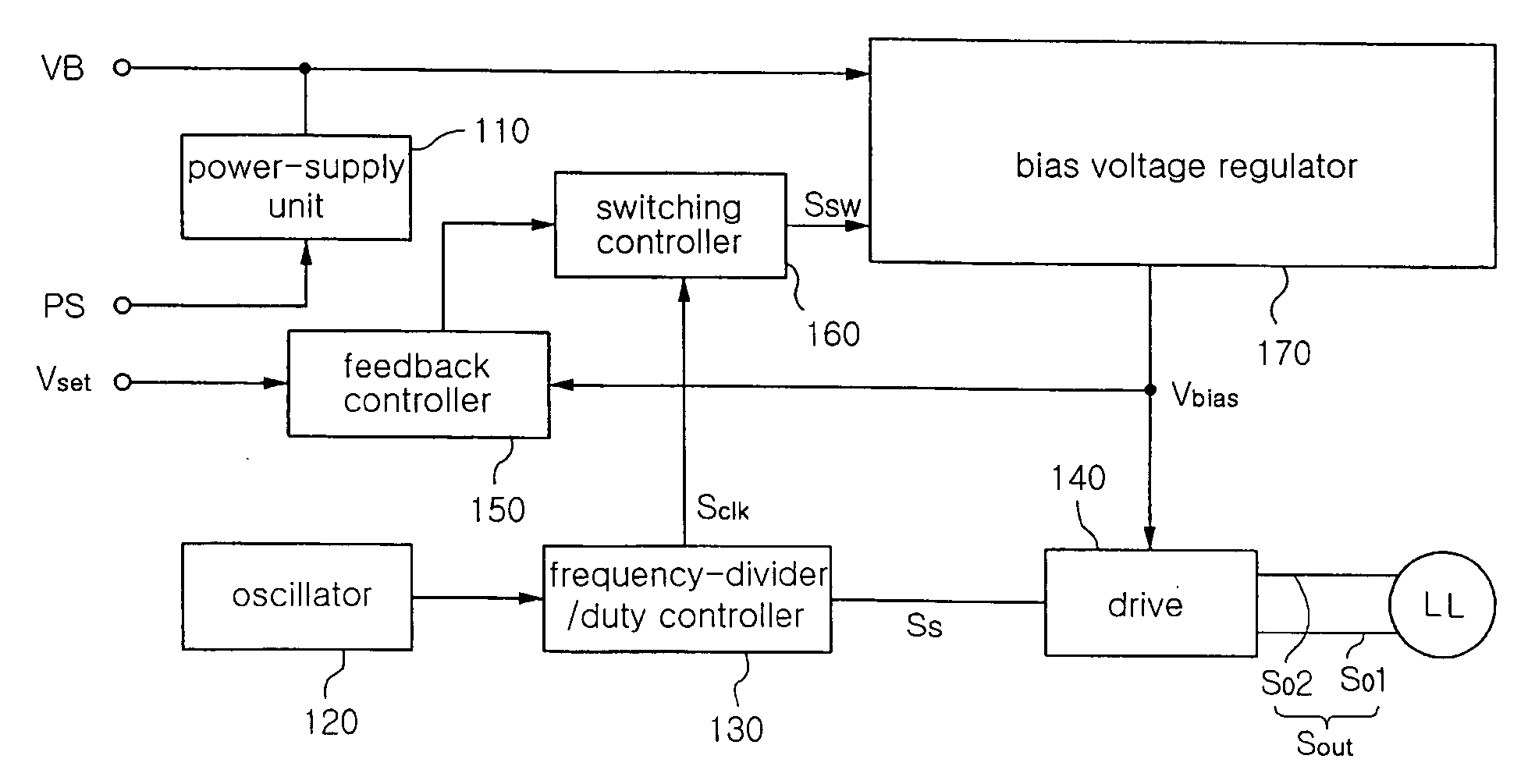
[0033]FIG. 3 is a block diagram illustrating a variable square-wave drive device in accordance with the present invention.

[0034] Referring to FIG. 3, the variable square-wave drive device acts as a device for controlling a pair of square-wave drive signals having opposite phases.

[0035] The variable square wave driving device of the present invention includes a power-supply unit 110 for receiving an input voltage VB, and transmitting a necessary voltage to individual components; an oscillator 120 for generating a cloc...


PUM

PropertyMeasurementUnit
voltageaaaaaaaaaa
frequenciesaaaaaaaaaa

Abstract

A variable square-wave drive device for controlling square waves using feedback- and bias-control methods. The variable square-wave drive device includes an oscillator for generating a clock pulse; a frequency-divider / duty controller for frequency-dividing the clock pulse received from the oscillator to generate a clock signal and a square-wave signal; a drive for amplifying the square-wave signal received from the frequency-divider / duty controller according to a bias voltage, generating first and second square-wave signals having opposite phases, and outputting the first and second square-wave signals as a square-wave drive signal; a feedback controller for comparing a predetermined voltage variable determined by a user with the bias voltage of the drive to generate a comparison result signal; a switching controller for generating a switching signal upon receiving the comparison result signal from the feedback controller; and a bias voltage regulator for charging / discharging the input voltage according to the switching signal received from the switching controller so that it can adjust the bias voltage of the drive.

Description

BACKGROUND OF THE INVENTION [0001] 1. Field of the Invention [0002] The present invention relates to a variable square-wave drive device for use in camera modules such as an HHP (Hand Held Phone), and more particularly to a variable square-wave drive device for controlling square waves using a feedback- or bias-control method to vary the square waves, such that it can correctly control a curvature of an LL (Liquid Lens), and can more precisely and stably control focus and zoom functions of a camera module. [0003] 2. Description of the Related Art [0004] Typically, two different liquids are contained in a transparent body of an LL, and individual curvatures of the liquids can be adjusted by a driving voltage, such that it is well known in the art that the focus and zoom functions of the camera module can be controlled without using additional mechanical mechanisms. [0005] Optical devices using liquid crystal lens have been disclosed in U.S. Pat. Nos. 4,190,330 and 6,433,770, which ar...

Claims


Application Information

Patent Timeline
Patent Type & Authority Applications(United States)
IPC IPC(8): G03B3/10G02B3/14G02B7/08G02F1/13G02F1/133G02F1/29G03B13/34G09G3/36H01R13/66H03K7/02H03K7/08H04B17/00
CPCG02F1/29G02F1/13306E02D29/0241E02D29/0266E02D2600/20E02D2600/40
Inventor MIN, BYOUNG OWNKIM, HYUN JINJEON, HYOUNG JUN
Owner SAMSUNG ELECTRO MECHANICS CO LTD
Why Eureka
Try Eureka