This helps you quickly interpret patents by identifying the three key elements:
Problems solved by technology
Method used
Benefits of technology
Benefits of technology
[0018] To solve these problems in the conventional method, it is an object of the present invention to provide a fingerprint sensor capable of enhancing a response speed and having a pointing function well suited for the manipulation.
Problems solved by technology
However, the above-described conventional pointing method has several problems as follows.
Therefore, the calculating speed becomes slower or the circuit scale becomes bigger.
In addition, in an area type fingerprint sensor, it takes some time to detect fingerprints and transfer data for a single display screen, thereby the detection period of the cursor cannot be faster.
As described in Non-Patent Document 1, when the number of detected pixel is decreased in order to faster the detection speed, the information of fingerprint unevenness is lost, which causes it difficult to detect the fingerprint center in a safe manner, thereby the enhancement of the operating speed cannot be compatible with the safe detection of the fingerprint center.
However, the finger is generally put in an inclined state to cause its area to be changed, or is slid in regardless of the finger center, so that the user not used to the manipulation may feel it difficult to implement the manipulation.
In addition, a neutral state in which the finger is not shifted is set to a reference state, however, it is difficult to automatically set the fingerprint center as the neutral state, and the user may feel it difficult to realize the neutral position, which causes a difficulty in intentionally stopping the pointer.
Method used
Image
Click on the blue label to locate the original text in one second.
Reading with bidirectional positioning of images and text.
Examples
first embodiment
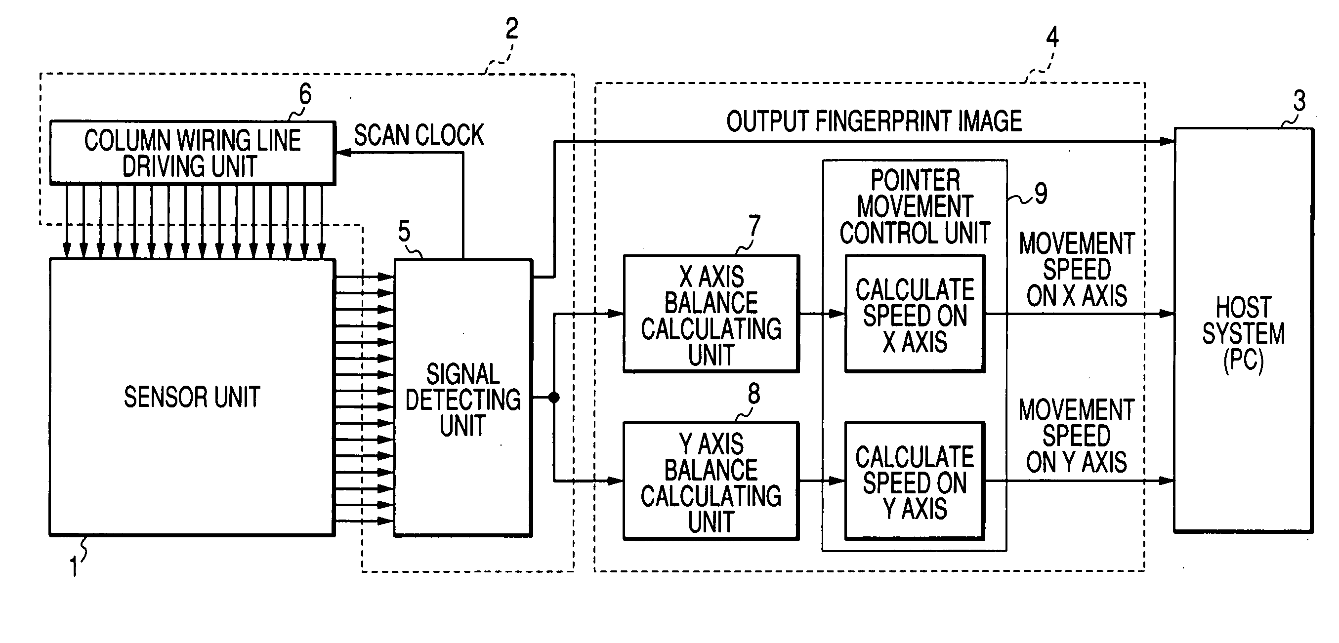
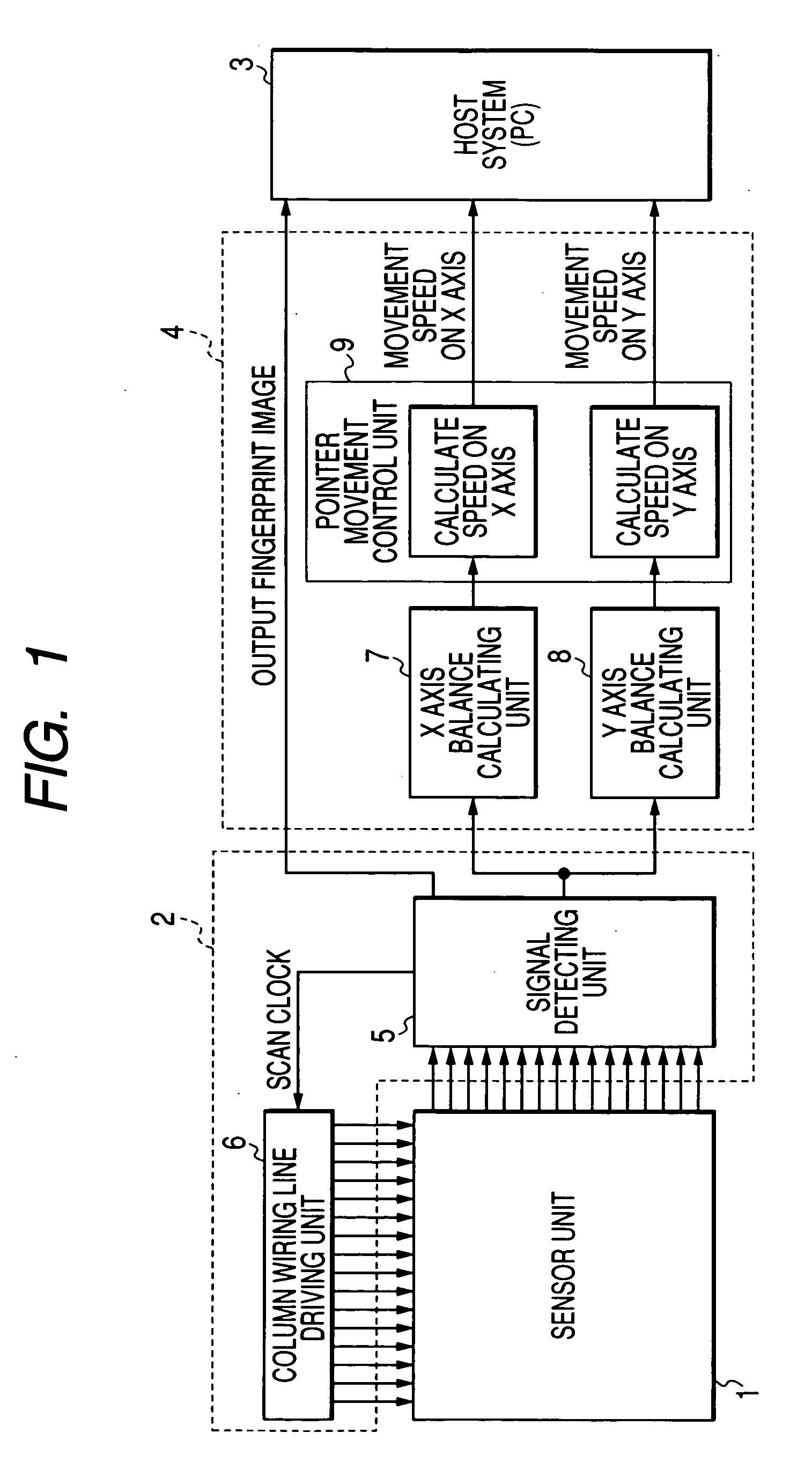
[0057]FIG. 1 is a block view illustrating a configuration example of the fingerprint sensor according to the first embodiment.
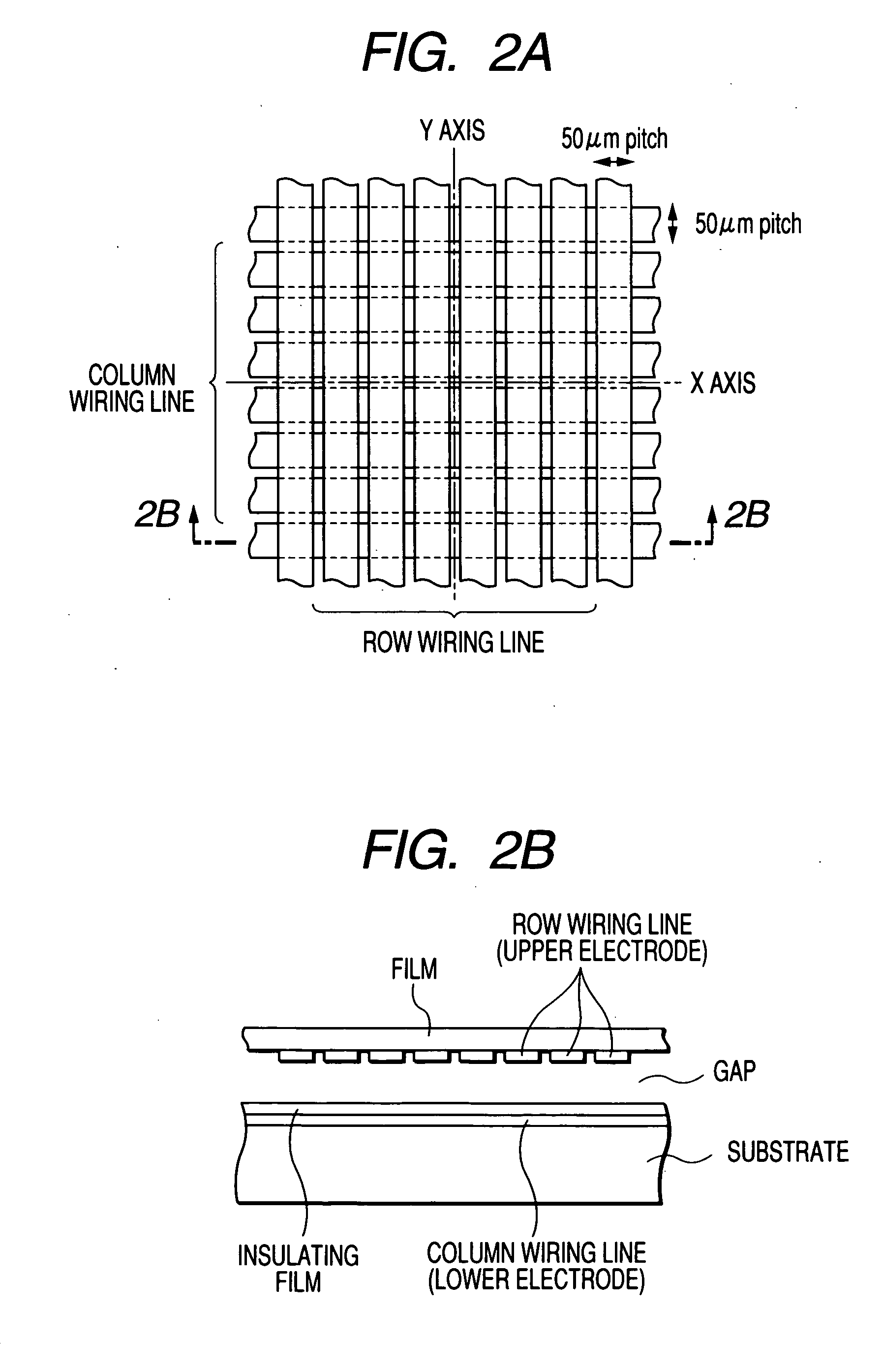
[0058] An area type fingerprint sensor as shown in FIG. 2 may be employed, for example, as the sensor used for the sensor unit 1 of FIG. 1, wherein a column wiring line is formed on a film and a row wiring line is correspondingly formed on a substrate, the column wiring line and the row wiring line are formed to correspond to each other with a gap being disposed therebetween (See FIG. 2B; cross-sectional view), and a capacitance of each intersection (See FIG. 2A; surface view) is detected. FIG. 3 shows an equivalent circuit of a capacitor formed at the intersection in a matrix of the column wiring line and the row wiring line of FIG. 2.
[0059] In this case, when a finger is put on the sensor unit 1, the film is deformed in response to the uneven shape of the fingerprint and a distance between the column wiring line and the row wiring line is changed, so that...
second embodiment
[0113] A fingerprint sensor according to the second embodiment will be described, however, which has the same configuration as that described in FIG. 1, and it differs from the first embodiment in a method of calculating movement speeds of the X axis balance calculating unit 7, the Y axis balance calculating unit 8, and the point movement control unit 9.
[0114] Hereinafter, the method of calculating movement speeds of the X axis balance calculating unit 7, the Y axis balance calculating unit 8, and the point movement control unit 9 will be described with reference to FIGS. 12 to 14 in accordance with the second embodiment.
[0115] The X axis balance calculating unit 7, when the balance output Px is calculated, divides the regions L and R of FIG. 4 into a plurality of blocks, respectively, and changes the weight (w1) for the sub blocks L1 and R1 at the central portion of the sensor unit 1, the weight (w3) for the sub blocks L3 and R3 at its peripheral portions, and the weight (w2) for...
third embodiment
[0119] The third embodiment, for example, assumes an application based on the movement of up and down of the pointer in the pointer processing corresponding to the scroll operation of image or the menu manipulation on the screen.
[0120] As is done with the first and second embodiments, in the method of independently processing the X axis and Y axis and combining the movement speeds of the obtained X and Y axis directions, it is apt to have the up and down balance (Y axis direction) out of balance to cause the inclined direction when the finger is shifted to move toward the traverse direction (x direction).
[0121] Accordingly, the X axis balance output Px is compared with the Y axis balance output Py, and a predetermined coefficient is multiplied to a smaller absolute value between these two outputs so that the balance output value is corrected to be smaller.
[0122] For example, the pointer movement control unit 9, when it detects Px>Py, adjusts the balance output so as to make the b...
PUM
Abstract
The fingerprint sensor of the present invention is a two-dimensional area typefingerprint sensor where a plurality of rows and a plurality of columns cross each other, which includes a signal detecting means for outputting a detection signal in a two-dimensional detection surface; an X axis balance calculating means having an output difference of the X axis direction as numerator and having a sum of the total outputs of the X axis direction as denominator to obtain a balance output of the X axis direction with a center of the detection surface being a reference and the X axis direction being in line-symmetrical with the Y axis passing through the center; a Y axis balance calculating means having an output difference of the Y axis direction in line-symmetrical with the X axis passing through the center as numerator and having a sum of the total outputs of the Y axis direction as denominator to obtain a balance output of the Y axis direction; and a pointer movement control means for controlling speed and movement direction of the pointer from the balance outputs of the X and Y axis directions.
Description
BACKGROUND OF THE INVENTION [0001] 1. Field of the Invention [0002] The present invention relates to a fingerprint sensor having a function of moving or pointing a cursor or the like in a display screen of a computer. [0003] 2. Description of the Related Art [0004] A fingerprint sensor which is the most favorable technology among biometrics is now being mounted in portable equipment such as a portable phone or the like. [0005] Accordingly, it is required to add another function such as a pointing as well as fingerprint detection to the fingerprint sensor. [0006] In the fingerprint sensor, a method of using a fingerprint pattern deformation as described below can be exemplified as the related art for implementing the pointing function (See Robotic Mechatronics Symposium held in May 23 (Friday) to 25 (Sunday), 2003 (Heisei 15) with a title of “the development of a new pointing device using fingerprint deformation” by Ikeda Atsutoshi (Nara Institute of Science and Technology), Kurita Y...
Claims
Application Information
Patent Timeline
Application Date:The date an application was filed.
Publication Date:The date a patent or application was officially published.
First Publication Date:The earliest publication date of a patent with the same application number.
Issue Date:Publication date of the patent grant document.
PCT Entry Date:The Entry date of PCT National Phase.
Estimated Expiry Date:The statutory expiry date of a patent right according to the Patent Law, and it is the longest term of protection that the patent right can achieve without the termination of the patent right due to other reasons(Term extension factor has been taken into account ).
Invalid Date:Actual expiry date is based on effective date or publication date of legal transaction data of invalid patent.

