Call processing system

Inactive Publication Date: 2005-09-29
BENQ CORP
View PDF7 Cites 55 Cited by
  • Summary
  • Abstract
  • Description
  • Claims
  • Application Information

AI Technical Summary

Benefits of technology

[0008] Accordingly, the object of the present invention is to improve efficiency of an emergency call center.

Problems solved by technology

Emergency call users can experience long waiting times before connecting to the operator, due to large volume, as much as several hours.
If the caller uses a mobile phone to call the emergency call processing center, the long waiting time can consume battery energy and the battery may become exhausted before connection.
Nonetheless, some emergency call requests still experience a long waiting period even with multiple processing units processing the call requests in parallel.
This problem is aggravated for mobile users as the calls may not connect to a local emergency service, but rather to a regional center.
Apart from serious delays, callers may have difficulty passing all relevant information to the operator in an efficient manner when the call is finally connected.
Mobile users suffering medical emergencies are likely to have difficulty reporting exact locations and conditions.

Method used


Image

  • Call processing system
  • Call processing system
  • Call processing system

Examples


first embodiment

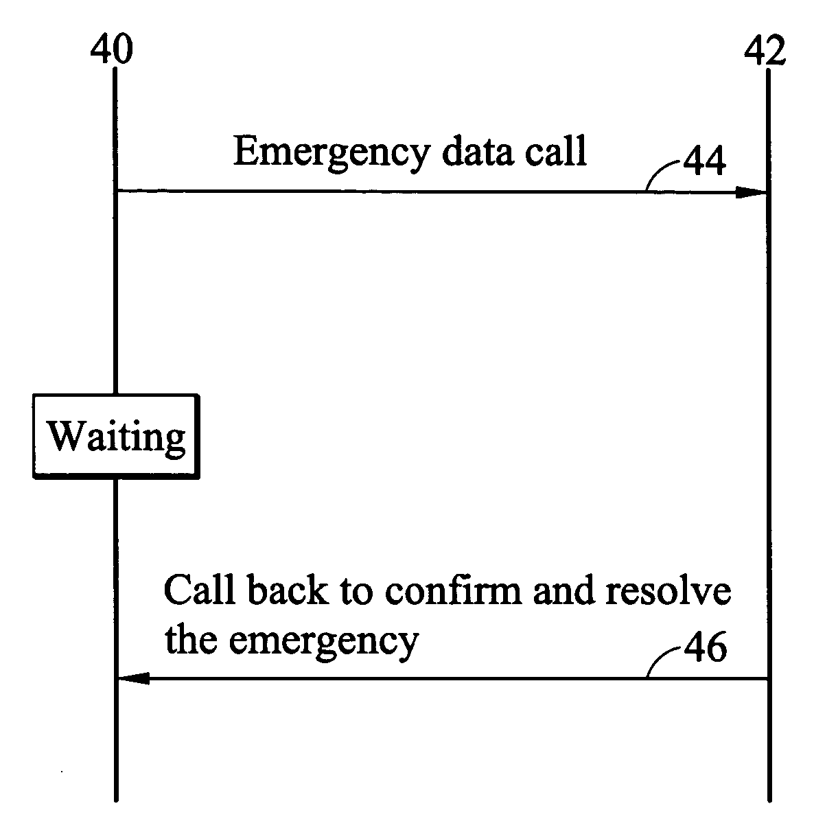
[0026] In the present invention, emergency calls are mobile-originating data calls transmitted through data networks rather than voice networks. FIG. 4a illustrates message flow between user equipment (UE) 40 and an emergency call center 42 of the two-phase emergency call model according to the present invention. UE 40 passes all available information associated with the mobile user and the UE 40 to the emergency call center 42 by sending an emergency data call 44. The UE 40 can comprise a cellular phone, a personal digital assistant (PDA), or any other communication device. FIG. 4b shows an example of the emergency data call 44 composition. The information carried by the emergency data call 44 can include caller phone number 441, voice message 442, image message 443, location information 444, and personal information 445. The emergency data call 44 is sent in a special format providing most information the emergency operator is likely require before dispatch appropriate assistance....

second embodiment

[0029] In the second embodiment, the emergency call center 52 sends a confirmation message 55 to UE 50 to acknowledge the arrival of the emergency data call 54, normally comprising registration identification (ID) 551 as shown in FIG. 5c. Upon receipt of confirmation message 55, the UE 50 changes to automatic hand-shaking mode. The emergency call center 52 then continues to collect relevant information from the UE 50 automatically, sending an alert message 56 to the UE 50. Examples of relevant information include current location, physical condition, current location audio / image data, and other information.

[0030] In conventional emergency call processing system, disorientation can present a common problem for callers, and it can take a long time for them to convey their precise location. The location of the mobile user can be obtained by a locating service provided in the communication system, for example, Global Positioning System (GPS). The emergency call center 52 requests curren...


PUM


Abstract

Call processing system and method for mobile users. The processing system identifies call urgency by categorizing incoming emergency data calls, and prioritizes the data calls accordingly. The emergency call processing method comprises submitting a data call to an emergency call center, placing the data call in a queuing system according to the priority level of the emergency, and waiting for an available processing unit to call back and address the emergency. During the waiting period, the emergency call center solicits information associated with the emergency, and user equipment returns the requested information automatically. The present invention improves efficiency of the emergency call center, ensuring that the most urgent emergency is served first. Additionally, the present invention conserves battery power of user equipment by collecting relevant information beforehand using data messages.

Description

BACKGROUND OF THE INVENTION [0001] 1. Field of the Invention [0002] The present invention relates to a call processing system, and more specifically, to a call processing system for mobile users. [0003] 2. Description of the Related Art [0004] Emergency call users can experience long waiting times before connecting to the operator, due to large volume, as much as several hours. Currently, emergency calls are handled by a one-phase emergency call model, wherein each caller employs a complete voice channel to the operator once the emergency call is connected. The operator maintains the communication with the caller until the emergency issue is resolved. Emergency calls are not guaranteed to be served in a First-in-first-out (FIFO) order if they are not placed in the queue successfully. If the caller uses a mobile phone to call the emergency call processing center, the long waiting time can consume battery energy and the battery may become exhausted before connection. [0005]FIG. 1 is a...

Claims


Application Information

Patent Timeline
IPC IPC(8): H04M3/00H04M3/51H04Q3/64H04Q7/38
CPCH04M3/5116H04M2203/2011H04M3/5166
Inventor CHENG, STEVEN D.
Owner BENQ CORP
Why Eureka
Try Eureka