Flexible shaft coupling

a flexible shaft and coupling technology, applied in the direction of yielding couplings, instruments, etc., can solve the problems of insufficient measurement, unusable flange hubs, and inability to transmit favorable rotational force, so as to reduce or dissipate the concentration of stress, improve the shape, and improve the effect of stress distribution

Active Publication Date: 2005-09-29
MIKI PULLEY
View PDF6 Cites 8 Cited by
  • Summary
  • Abstract
  • Description
  • Claims
  • Application Information

AI Technical Summary

Benefits of technology

[0007] In view of such problems of the prior art, a primary object of the present invention is to provide a flexible shaft coupling provided with a slit having an improved shape that can reduce or dissipate the concentration of stress and achieve more even stress distribution, to whereby avoid generation of cracking or any other damage to the shaft coupling and improve reliability and durability of the coupling.

Problems solved by technology

This may prohibit favorable rotational force transmission, and in an extreme case, the flange hub may become unusable.
However, such a measure is not sufficient and further improvement is desired.

Method used


Image

  • Flexible shaft coupling
  • Flexible shaft coupling
  • Flexible shaft coupling

Examples


Embodiment Construction

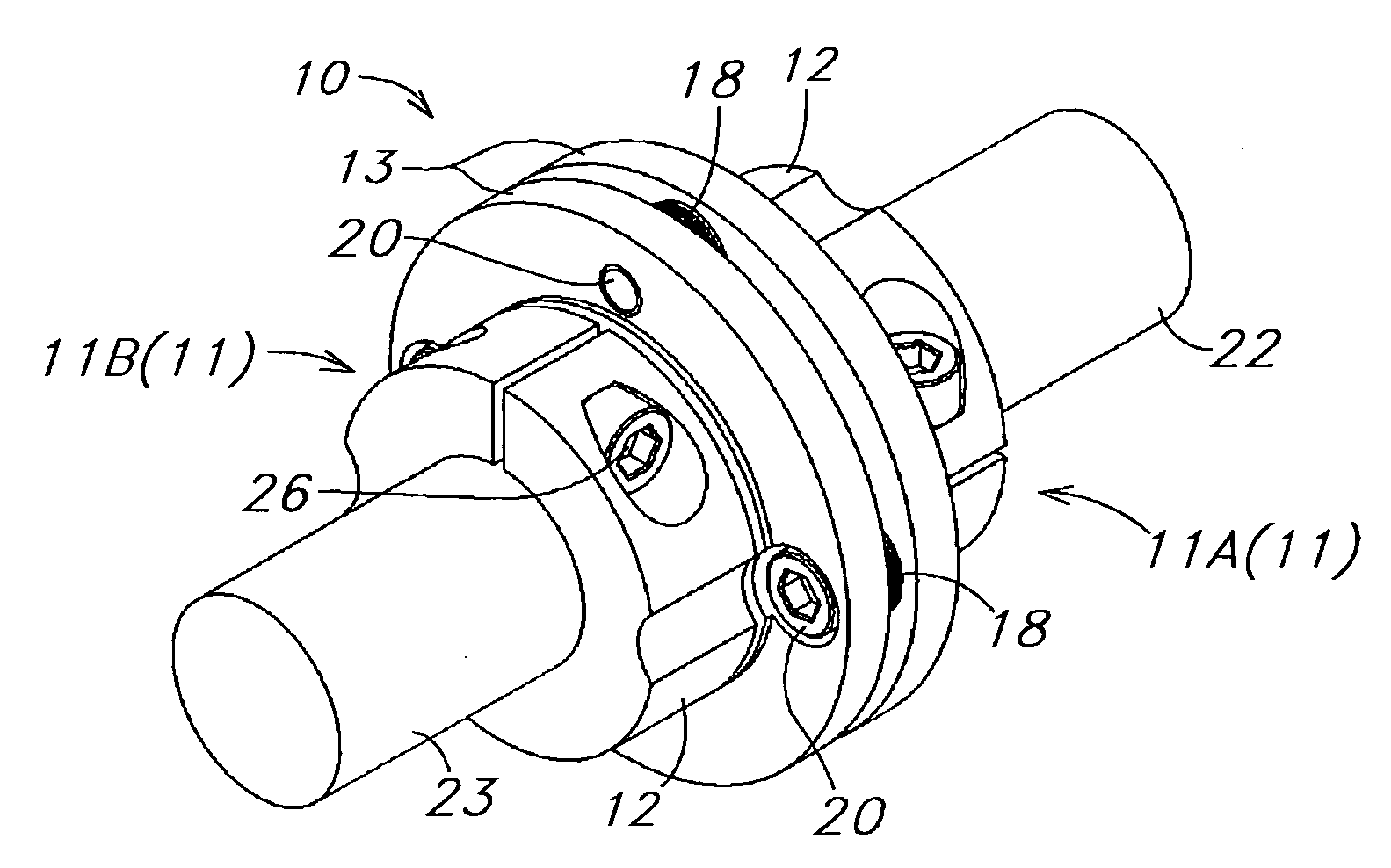
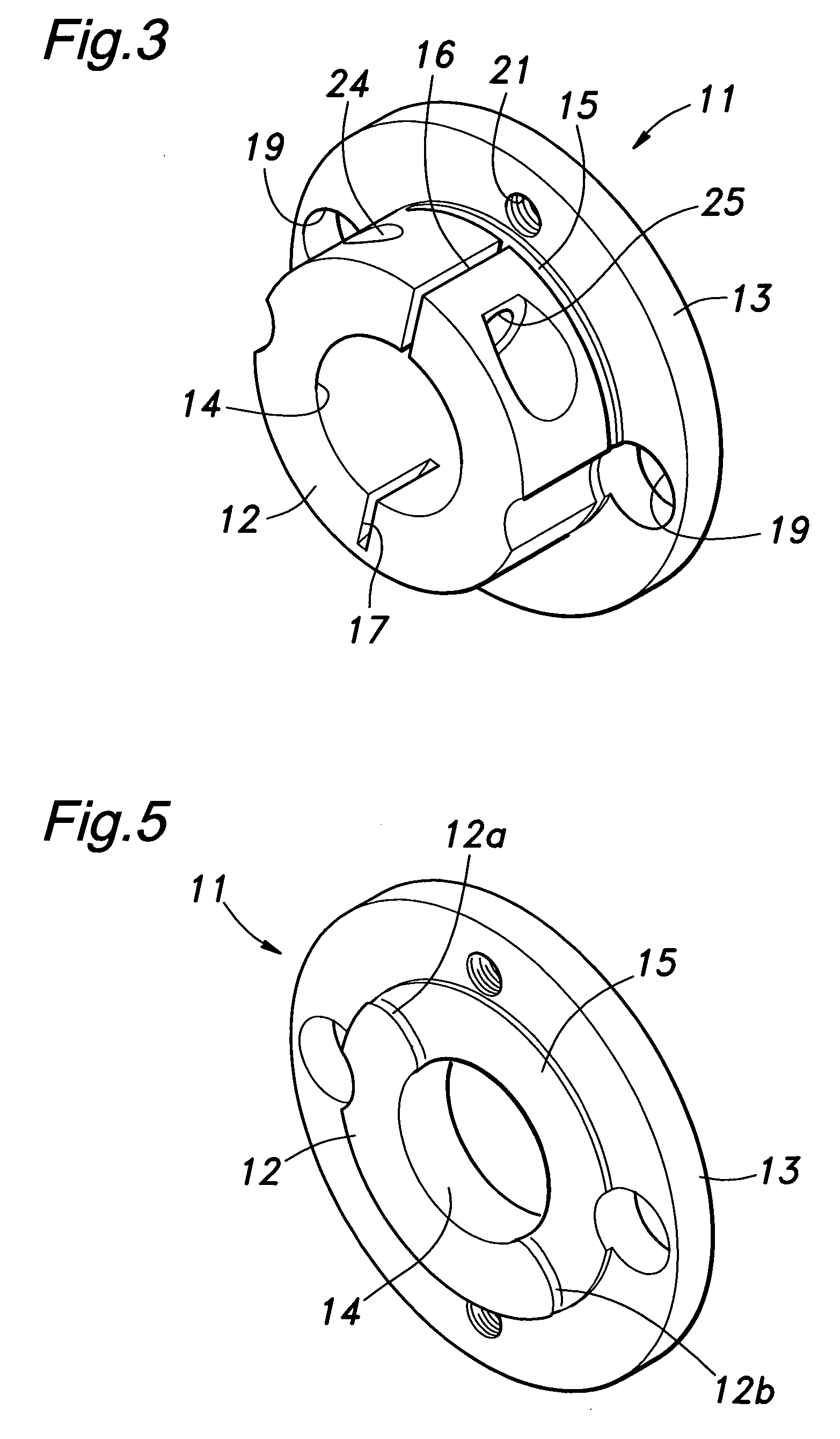
[0024]FIG. 3 is a perspective view showing a flange hub 11 used as a main body of a flexible shaft coupling 10 according to one embodiment of the present invention. The flange hub 11 is of a tubular shape having a boss portion 12 and a flange portion 13 which is integrally provided at one axial end of the boss portion 12. The flange hub 11 is formed at its center with an axial bore 14 for fittingly receiving a shaft to be connected. The boss portion 12 is formed with a circumferential slit 15 that extends circumferentially or in a direction perpendicular to the axis of the hub 11 at a position near a border with the flange portion 13 (see FIG. 5). The boss portion 12 is further provided with an axial slit 16 and an inner groove or notch 17 which are located circumferentially opposite to each other and extend in the axial direction.

[0025] As shown in FIG. 4, the flexible shaft coupling 10 can be constituted by a pair of identical flange hubs 11 (11A, 11B) which are arranged such tha...


PUM


Abstract

The present invention provides a flexible shaft coupling, comprising a tubular hub made of a rigid material, wherein the hub is provided with a slit extending substantially circumferentially for providing flexibility to the hub, the hub having an axial bore so that a rotational force of a drive rotation shaft received in the axial bore at one end of the hub can be transmitted to a driven rotation shaft attached to the other end of the hub, wherein circumferential ends of a part of the hub adjoining the slit are each provided with a convex shape having an arcuately receding surface at least at an outer peripheral portion.

Description

TECHNICAL FIELD [0001] The present invention relates to a flexible shaft coupling which is used to connect a drive rotation shaft and a driven rotation shaft to transmit power therebetween, and can flex to keep the connection when a misalignment, such as eccentricity, angular displacement or thrust displacement, is caused between the drive and driven rotation shafts. Particularly, the present invention relates to a flexible shaft coupling comprising a main body (hub) formed with one or a plurality of slits (grooves) for providing flexibility to the hub. BACKGROUND OF THE INVENTION [0002] Various flexible shaft couplings have been proposed in the past (see, for example, Japanese Utility Model Application Laid-Open No. 5-6226, Japanese Utility Model Application Laid-Open No. 6-78631, Japanese Patent Application Laid-Open No. 8-226456, Japanese Patent Application Laid-Open No. 10-47365 or Japanese Patent Registration No. 3382585). These flexible shaft couplings comprise a hub consistin...

Claims


Application Information

Patent Timeline
Patent Type & Authority Applications(United States)
IPC IPC(8): F16D3/74F16D3/56F16D3/72F16D3/76F16D13/50
CPCF16D3/72G06F15/16G06F2213/0042
Inventor ENDOU, SEIJI
Owner MIKI PULLEY
Why Eureka
Try Eureka