

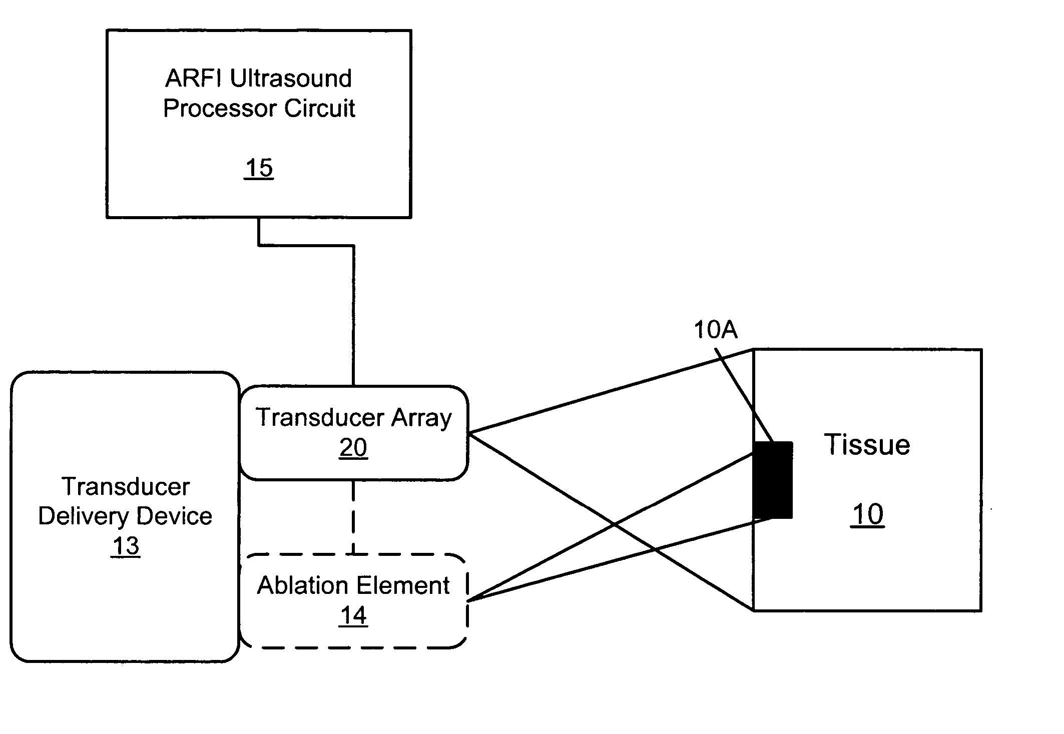
Methods, systems, and computer program products for acoustic radiation force impulse (ARFI) imaging of ablated tissue
a technology of acoustic radiation force impulse and ablation tissue, applied in the field of ultrasonography, can solve the problems of bubbles that cannot be characterized with any degree of precision, and sonography may not perform well in characterizing the size or boundary of lesions,
- Summary
- Abstract
- Description
- Claims
- Application Information
AI Technical Summary
Benefits of technology
Problems solved by technology
Method used
Image

Examples
example 1
Acoustic Radiation Force Impulse Imaging of Myocardial Radiofrequency Ablation: In Vivo Results
[0088] Acoustic Radiation Force Impulse (ARFI) imaging techniques were used to monitor radiofrequency (RF) ablation procedures in in vivo sheep hearts. Additionally, ARFI M-Mode imaging methods were used to interrogate both healthy and ablated regions of myocardial tissue. While induced cardiac lesions were not visualized well in conventional B-Mode images, ARFI images of ablation procedures allowed determination of lesion size, location, and shape through time. ARFI M-Mode images were capable of distinguishing differences in mechanical behavior through the cardiac cycle between healthy and damaged tissue regions. As conventional sonography is often used to guide ablation catheters, ARFI imaging may be a convenient modality for monitoring lesion formation in vivo.
Imaging / Data Acquisition
[0089] Experiments were performed with a Siemens Antares scanner (Siemens Medical Solutions USA, Inc...
example 2
[0116] The ability of ARFI imaging to monitor the ablation of soft tissues both ex vivo and in vivo was investigated. Thermal lesions were induced both in freshly excised bovine liver samples and in myocardialtissue of live sheep. While conventional sonography was unable to visualize induced lesions, ARFI imaging was capable of monitoring lesion size-and boundaries. Agreement was observed between lesion size in ARFI images and in results from pathology.
Imaging / Data Acquisition
[0117] Experiments were performed with a Siemens Antares scanner (Siemens Medical Solutions USA, Inc., Ultrasound Division, Issaquah, Wash.) that has been modified to provide users with the ability to specify acoustic beam sequences and intensities, as well as access raw radio frequency data. A Siemens VF10-5 linear array was used to acquire data. Beam sequences during ARFI data collection consisted of both tracking and pushing beams. The tracking beams were standard B-mode pulses (6.67 MHz center frequency,...
example 3
[0133] The ability of acoustic radiation force impulse (ARFI) imaging to visualize thermally- and chemically-induced lesions in soft tissues was investigated. Lesions were induced in freshly excised bovine liver samples. Chemical lesions were induced via the injection of formaldehyde, and thermal lesions were created using a radiofrequency ablation system. While conventional sonography was unable to visualize induced lesions, ARFI imaging was capable of monitoring lesion size and boundaries. Agreement was observed between lesion size in ARFI images and in results from pathology. ARFI imaging may be a promising modality for monitoring lesion development in situations where sonography is already involved as a guiding mechanism, such as in procedures requiring precise catheter placement.
[0134] Experiments were performed with a Siemens Anteres scanner (Siemens Medical Solutions USA, Inc., Ultrasound Division, Issaquah, Wash.) that has been modified to provide users with the ability to ...
PUM
 Abstract
Description
Claims
Application Information