
Apparatus for converting a clamp into an electrophysiology device

a technology of electrophysiology and apparatus, which is applied in the direction of medical science, surgical instrument details, surgery, etc., can solve the problems of affecting the normal activation of the left and right atria, and suffering consequences, so as to achieve the effect of quick conversion of a conventional clamp and eliminating costs

Inactive Publication Date: 2005-09-29
BOSTON SCI SCIMED INC
View PDF99 Cites 46 Cited by
  • Summary
  • Abstract
  • Description
  • Claims
  • Application Information

AI Technical Summary

Benefits of technology

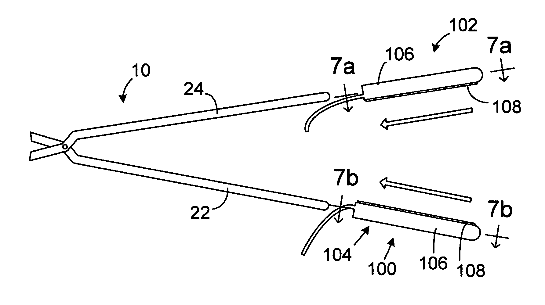
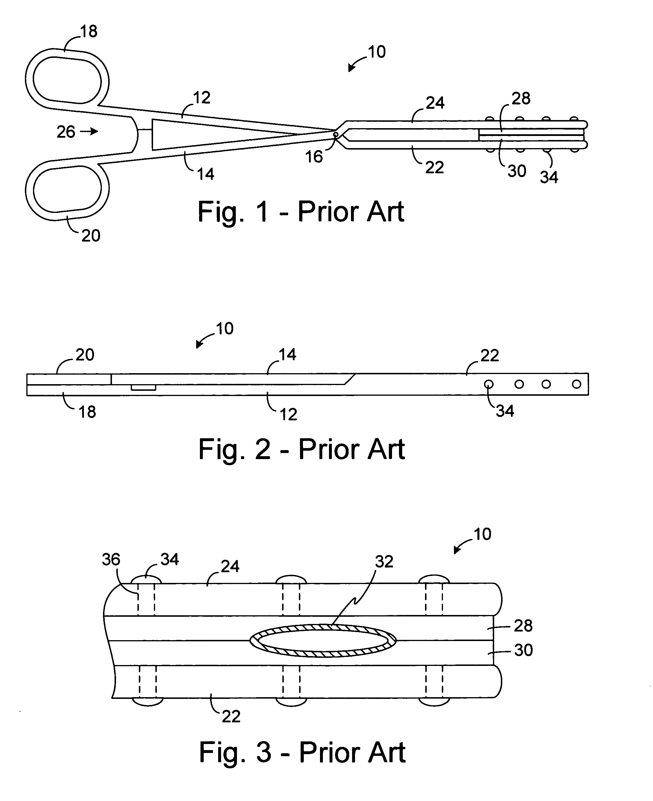
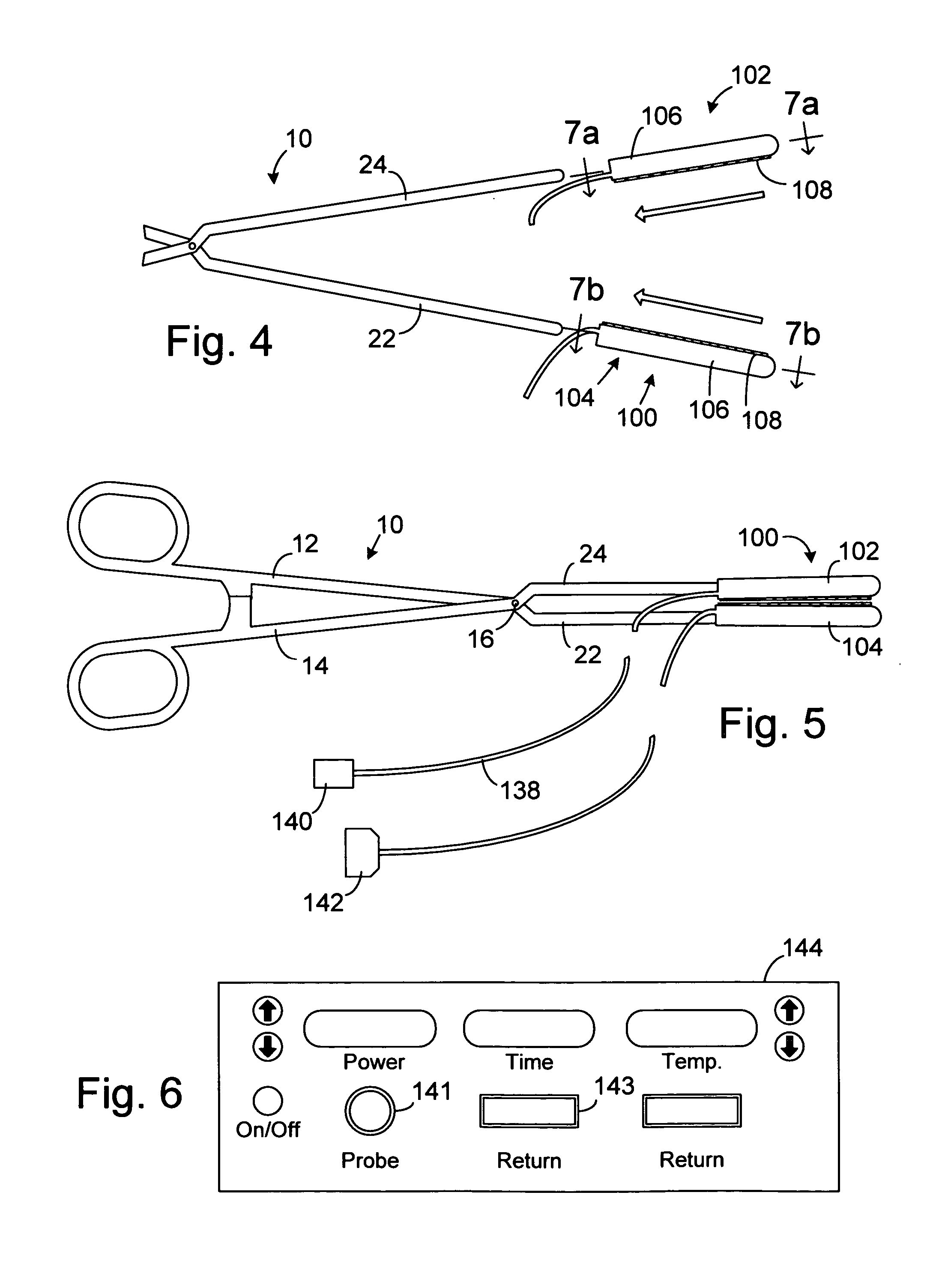
[0015] An apparatus for use with a clamp in accordance with one embodiment of a present invention includes a base member configured to be secured to the clamp and at least one energy transmission device carried by the base member. Such an apparatus provides a number of advantages. For example, such an apparatus may be used to quickly convert a conventional clamp into an electrophysiology device. In those instances where a procedure requires a number of different clamps, the apparatus can be moved from clamp to clamp, thereby eliminating the costs associated with providing a variety of different clamps with energy transmission devices permanently secured thereto.
[0016] An apparatus for use with a clamp and a probe that carries at least one energy transmission device in accordance with one embodiment of a present invention includes a base member configured to be secured to the clamp and an engagement device associated with the base member and configured to engage the probe. Such an apparatus provides a number of advantages. For example, such an apparatus may be used to quickly convert a conventional clamp into an electrophysiology device and to achieve better (or merely different) tissue / energy transmission device contact than could be achieved with the probe itself. Additionally, in those instances where a procedure requires a number of different clamps, the apparatus can be moved from clamp to clamp, thereby eliminating the costs associated with providing a variety of different clamps with energy transmission devices permanently secured thereto.
[0017] A clamp in accordance with one embodiment of a present invention includes first and second clamp members, at least one of which is malleable, and a movement apparatus that moves at least one of the first and second clamp members relative to the other. Such a clamp provides a number of advantages. For example, the malleable clamp member allows physicians to readily reconfigure the clamp, thereby reducing the number of clamps that must be provide for a particular surgical procedure.
[0018] A surgical system in accordance with one embodiment of a present invention includes a clamp with first and second clamp members and a device that removably mounts at least one electrode on at least one of the first and second clamp members. Such a clamp provides a number of advantages. For example, the system may be used both as a conventional clamp and an electrophysiology device.

Problems solved by technology

These wavelets, called “reentry circuits,” disrupt the normally uniform activation of the left and right atria.
Because of a loss of atrioventricular synchrony, the people who suffer from atrial fibrillation and flutter also suffer the consequences of impaired hemodynamics and loss of cardiac efficiency.
They are also at greater risk of stroke and other thromboembolic complications because of loss of effective contraction and atrial stasis.
However, the maze procedure is technically difficult to do.
It also requires open heart surgery and is very expensive.
Thus, despite its considerable clinical success, only a few maze procedures are done each year.

Method used


Image

  • Apparatus for converting a clamp into an electrophysiology device
  • Apparatus for converting a clamp into an electrophysiology device
  • Apparatus for converting a clamp into an electrophysiology device

Examples


Embodiment Construction

[0057] The following is a detailed description of the best presently known modes of carrying out the inventions. This description is not to be taken in a limiting sense, but is made merely for the purpose of illustrating the general principles of the inventions.

[0058] The detailed description of the preferred embodiments is organized as follows: [0059] I. Energy Transmission Assemblies [0060] II. Energy Transmission Devices, Temperature Sensing and Power Control [0061] III. Tissue Cooling Apparatus [0062] IV. Probe Support Devices [0063] V. Clamp With Malleable Clamp Members

The section titles and overall organization of the present detailed description are for the purpose of convenience only and are not intended to limit the present inventions.

[0064] This specification discloses a number of structures, mainly in the context of cardiac ablation, because the structures are well suited for use with myocardial tissue. Nevertheless, it should be appreciated that the structures are ap...


PUM

PropertyMeasurementUnit
lengthaaaaaaaaaa
lengthaaaaaaaaaa
lengthaaaaaaaaaa

Abstract

An apparatus for use with a clamp including a base member configured to be secured to the clamp and at least one energy transmission device carried by the base member. An apparatus for use with a clamp and a probe that carries at least one energy transmission device including a base member configured to be secured to the clamp and an engagement device associated with the base member and configured to engage the probe. A clamp including first and second clamp members, at least one of which is malleable, and a movement apparatus that moves at least one of the first and second clamp members relative to the other. A surgical system including a clamp with first and second clamp members and a device that removably mounts at least one electrode on at least one of the first and second clamp members.

Description

CROSS-REFERENCE TO RELATED APPLICATIONS [0001] This application is a continuation of U.S. application Ser. No. 10 / 079,944, filed Feb. 19, 2002.BACKGROUND OF THE INVENTIONS [0002] 1. Field of Inventions [0003] The present inventions relate generally to structures for positioning diagnostic and therapeutic elements within the body and, more particularly, to devices which are particularly well suited for the treatment of cardiac conditions. [0004] 2. Description of the Related Art [0005] There are many instances where diagnostic and therapeutic elements must be inserted into the body. One instance involves the treatment of cardiac conditions such as atrial fibrillation and atrial flutter which lead to an unpleasant, irregular heart beat, called arrhythmia. [0006] Normal sinus rhythm of the heart begins with the sinoatrial node (or “SA node”) generating an electrical impulse. The impulse usually propagates uniformly across the right and left atria and the atrial septum to the atrioventr...

Claims


Application Information

Patent Timeline
Patent Type & Authority Applications(United States)
IPC IPC(8): A61B18/12A61B18/00A61B18/14A61B18/18
CPCA61B18/14A61B2017/00296A61B2018/00023A61B2018/1495A61B2018/00125A61B2018/1472A61B2018/00065
Inventor PHAN, HUY D.
Owner BOSTON SCI SCIMED INC
Learn More