System with a screwdriver and a bone screw

Inactive Publication Date: 2005-09-29
INNOVATIONS MEDICAL
View PDF8 Cites 32 Cited by
  • Summary
  • Abstract
  • Description
  • Claims
  • Application Information

AI Technical Summary

Benefits of technology

[0011] Consequently, the object of the present invention is to provide a system comprising a bone screw and a screwdriver, with whi

Problems solved by technology

Furthermore, unlike in the state of the art described in the introduction, additional manipulations of the screwdriver to hold the bone screw

Method used


Image

  • System with a screwdriver and a bone screw
  • System with a screwdriver and a bone screw
  • System with a screwdriver and a bone screw

Examples


Example

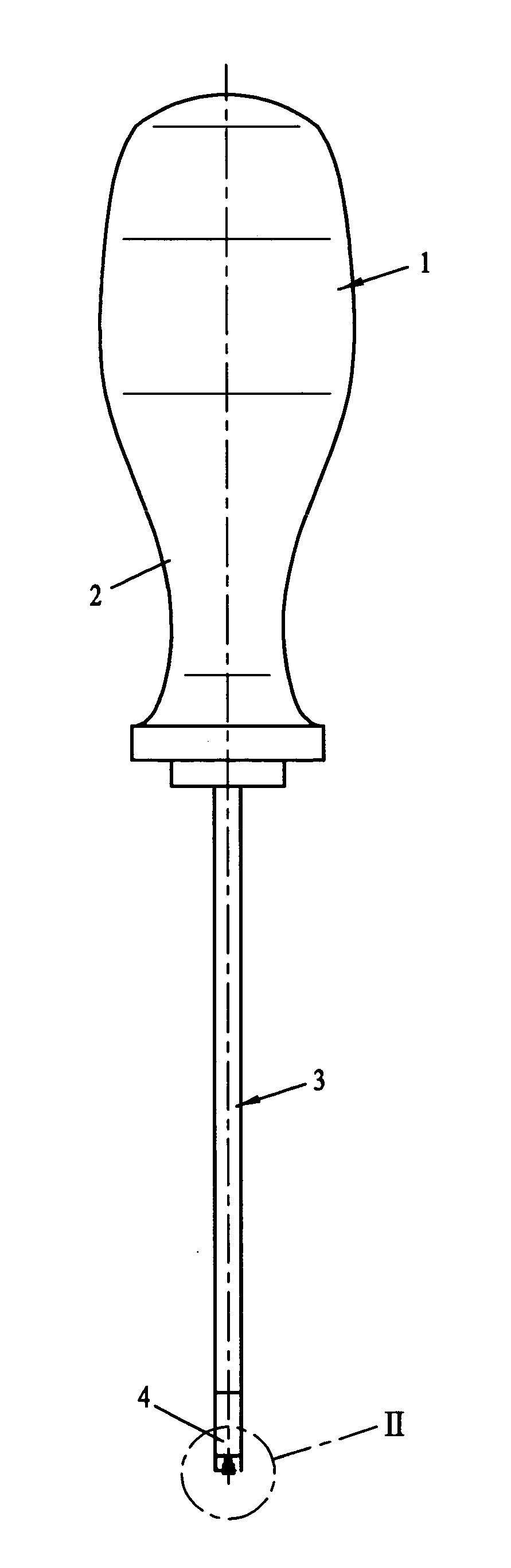
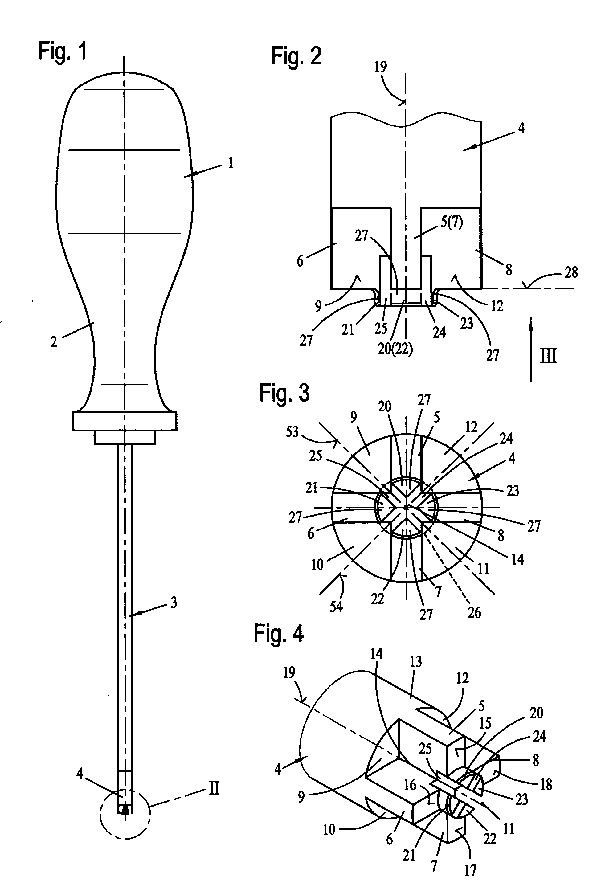
[0067] Referring to the drawings in particular, FIG. 1 shows a side view of a screwdriver 1, which has a grip part 2 for actuation in the known manner. This grip part 2 is on connection with a tool shank 3 in such a way that they rotate in unison, the tool shank having, at its end located opposite the grip part 2, a tool 4, which is used to rotatingly actuate a bone screw. Provisions may be made here for the tool shank 3 to be attached to the grip part 2 such that it can be replaced with other tool shanks with different tools.

[0068]FIG. 2 shows an enlarged view II of this tool 4 from FIG. 1, and it can be recognized in connection with FIG. 3 that this tool 4 has a total of four radially extending tool blades 5, 6, 7 and 8. These four tool blades 5 through 8 are formed by cutouts 9, 10, 11 and 12 which have an essentially triangular cross section.

[0069] As is apparent from FIGS. 3 and 4, the tool 4 forms a rotationally symmetrical, cylindrical blade shank 13, in which the cutouts 9...


PUM


Abstract

A system is provided with a screwdriver and a bone screw (30), wherein the screwdriver has a tool (4), which is provided with at least two radially and axially extending tool blades (5, 6, 7, 8), which can be caused to engage groove-like blade slots (36, 38) of the bone screw (30) in a positive-locking manner. To improve the handling of a bone screw (30) even in case of the smallest possible dimensions, provisions are made according to the present invention for the tool blades (5, 6, 7, 8) to form at least one elastic clamping section (20, 21, 22, 23), with which the tool (4) can be caused to clampingly engage the bone screw (30) in the area of the blade slots (36, 38).

Description

CROSS REFERENCE TO RELATED APPLICATIONS [0001] This application claims the benefit of priority under 35 U.S.C. § 119 of German Application DE 20 2004 004 844.2 filed Mar. 27, 2004, the entire contents of which are incorporated herein by reference. FIELD OF THE INVENTION [0002] The present invention pertains to a system with a screwdriver and a bone screw, wherein the screwdriver has a tool, which is provided with at least two radially and axially extending tool blades, which can be caused to engage groove-like blade slots of the bone screw in a positive-locking manner. BACKGROUND OF THE INVENTION [0003] Bone screws are used, for example, for osteosynthesis either in conjunction with bone plates or also individually. Small fragment screws, in particular, also so-called cortex screws, are used after cranial injuries following accidents as well as in orthopedic maxillofacial surgery, in hand surgery and, in various dimensions, in other areas as well. Such small fragment screws are extr...

Claims


Application Information

Patent Timeline
IPC IPC(8): A61B17/86A61B17/88B25B15/00B25B23/10F16B23/00
CPCA61B17/8605A61B17/861A61B17/8877A61B17/8886F16B23/0023B25B15/007B25B23/106B25B23/108B25B15/005
Inventor KREIDLER, WINFRIED
Owner INNOVATIONS MEDICAL
Why Eureka
Try Eureka