Automatic open/close device for toilet seat or toilet cover

a technology of toilet seat, which is applied in the direction of bathroom covers, bathroom accessories, domestic applications, etc., can solve the problems of not applying excessive load at the rotating shaft side to the planetary gear mechanism, and achieve the effect of miniaturizing the automatic lifting and lowering device, reducing the thickness of the gear itself, and increasing the contact area

Active Publication Date: 2005-10-06
TOTO LTD
View PDF2 Cites 29 Cited by
  • Summary
  • Abstract
  • Description
  • Claims
  • Application Information

AI Technical Summary

Benefits of technology

[0014] In the invention according to claim 34, in addition to the invention according to claim 33, a helical gear is used as the pinion. The helical gear is thinner than a spur gear, but can secure more contact area. Using the helical gear makes it possible to reduce the thickness of the gear itself while securing the strength of the gear so that the speed reduction gear train is made compact. Therefore, it is possible to miniaturize the automatic lifting and lowering device.

Problems solved by technology

Even if an excessive load is applied to the rotating shaft in such cases that the toilet seat or the toilet cover is manually held during automatic lifting and lowering operations, the excessive load at the rotating shaft side is not applied to the planetary gear mechanisms.

Method used


Image

  • Automatic open/close device for toilet seat or toilet cover
  • Automatic open/close device for toilet seat or toilet cover
  • Automatic open/close device for toilet seat or toilet cover

Examples


first embodiment

[0082]FIG. 11 shows an example in which the automatic lifting and lowering devices 30 are disposed in parallel with each other as an automatic lifting and lowering device 30a for the toilet seat 12 and an automatic lifting and lowering device 30b for the toilet cover 13. The automatic toilet seat lifting and lowering device 30a and the automatic toilet cover lifting and lowering device 30b are intensively installable on one side in accordance with relation with other functional parts in the toilet seat apparatus 10 as described above so that it is possible to further make the design of housing easier.

[0083] When the automatic lifting and lowering devices 30a and 30b are intensively installed on one side like this, the automatic lifting and lowering device 30a for the toilet seat 12 and the automatic lifting and lowering device 30b for the toilet cover 13, as shown in FIG. 12, constitute the integral functional parts storage tube 31. Therefore, it is possible to reduce the size and ...

seventh embodiment

[0090] Then, with reference to FIGS. 21 to 32, an automatic lifting and lowering device for a toilet seat or a toilet cover according to the present invention will be described. The same reference numerals as those in FIGS. 1 to 20 are used in FIGS. 21 to 32, but they do not relate to each other. All reference numerals hereinafter described designate reference numerals shown in FIGS. 21 to 32.

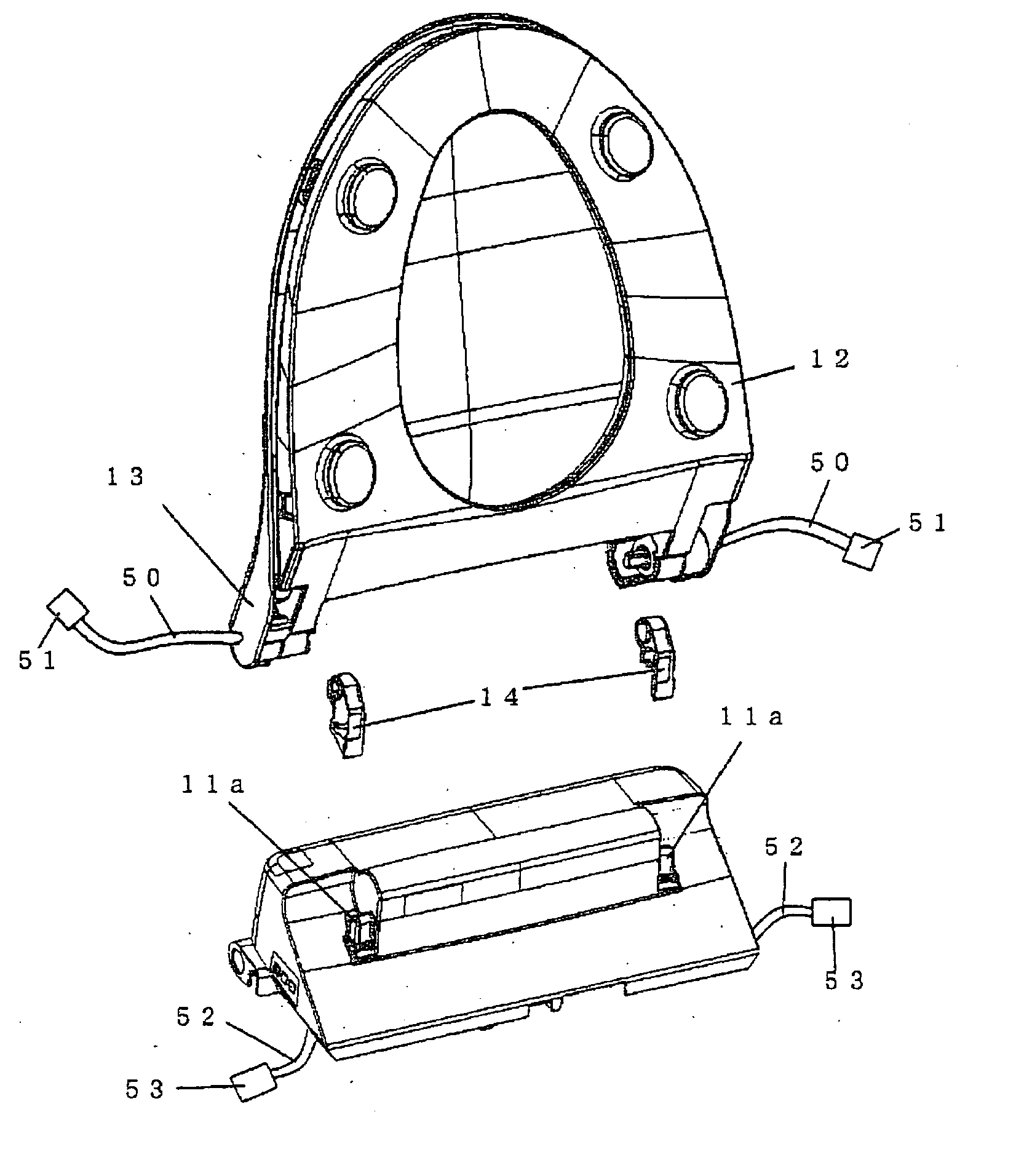
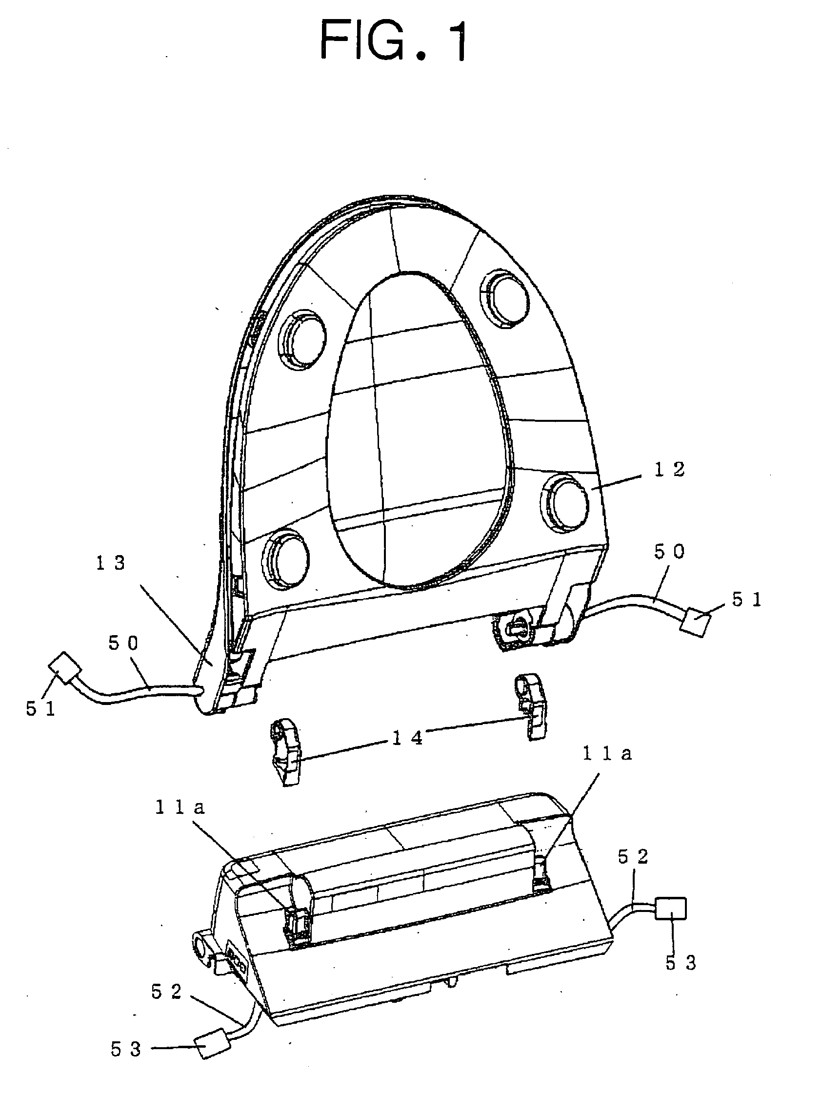
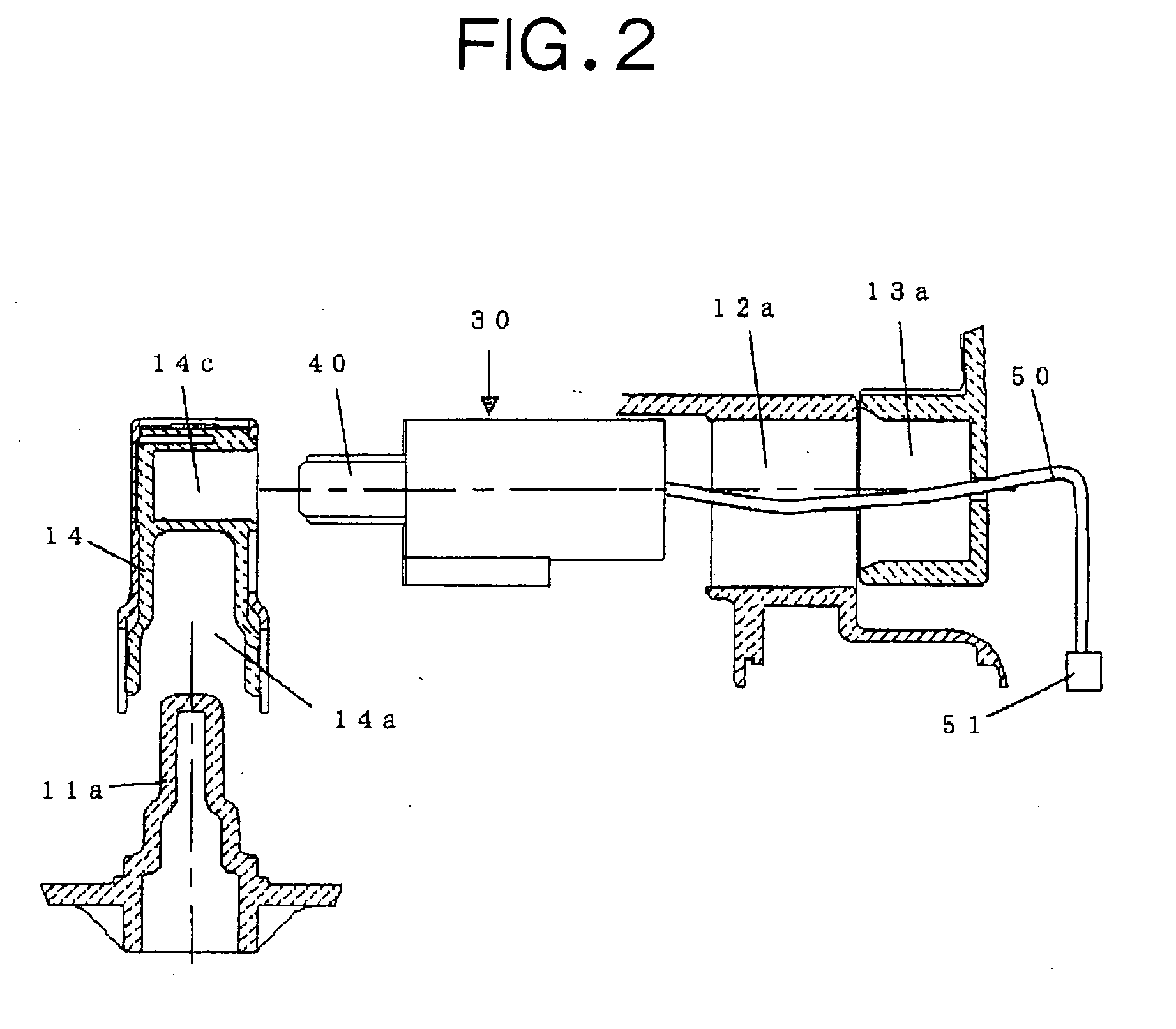
[0091]FIG. 21 is a perspective view of a toilet seat apparatus 10, in which an automatic lifting and lowering device for a toilet seat or a toilet cover according to the seventh embodiment of the present invention is installed. FIG. 22 is an exploded perspective view which explains an attachment position of the automatic lifting and lowering device for the toilet seat or the toilet cover. FIG. 23 is a sectional view of the toilet seat apparatus 10 in which an automatic toilet seat lifting and lowering device 30 is installed, and FIG. 24 is a sectional view of the toilet seat apparatus 10 in whi...


PUM


Abstract

An automatic lifting and lowering device for a toilet seat or a toilet cover usable for a toilet seat provided with a function of washing a body with hot water, which requires reduced size and weight, comprising a rotating shaft (40) rotated together with the toilet seat or the toilet cover, a drive motor (32) rotating the rotating shaft (40) in normal and reverse directions, and a speed reduction gear train (33), wherein the drive force of the drive motor (32) is transmitted to the rotating shaft (40) through the speed reduction gear train (33) to automatically lift and lower the toilet seat or toilet cover, whereby the automatic lifting and lowering device itself can be formed compact by using a planetary gear mechanism for the speed reduction gear train (33).

Description

TECHNICAL FIELD [0001] The present invention relates to an automatic lifting and lowering device for a toilet seat or a toilet cover of a Western-style toilet, and more specifically, the present invention relates to a device that automatically lifts and lowers the toilet seat or the toilet cover on an individual basis. BACKGROUND ART [0002] As for an automatic lifting and lowering device for a toilet seat or a toilet cover of a Western-style toilet, a technology disclosed in Unexamined Japanese Patent Publication No. Hei 11-216083 is known, in which each of the toilet seat and the toilet cover is provided with the separate automatic lifting and lowering device. In the automatic lifting and lowering device, an output shaft of a drive motor is coupled with a rotating shaft thereof through a plurality of gear trains so that the output shaft and the rotating shaft are formed nonconcentrically from each other. [0003] The foregoing device requires large attachment area (with respect to a ...

Claims


Application Information

Patent Timeline
Patent Type & Authority Applications(United States)
IPC IPC(8): A47K13/10
CPCA47K13/10
Inventor HAYASHI, RYOSUKETERADA, YOSHIROMIYAMOTO, HIROOMIHASHIDUME, KENJI
Owner TOTO LTD
Why Eureka
Try Eureka