Process for producing a pulley for a continuously variable belt drive transmission

a technology of continuously variable belt drive and transmission process, which is applied in the direction of gearing, manufacturing tools, hoisting equipment, etc., can solve the problems of less dimensional accuracy of the resultant tapered surface, and the friction coefficient of the surface of the pulley which is contacted, and achieve the effect of reducing the height of the microprojections

Inactive Publication Date: 2005-10-06
JATCO LTD
View PDF7 Cites 37 Cited by
  • Summary
  • Abstract
  • Description
  • Claims
  • Application Information

AI Technical Summary

Benefits of technology

[0004] The present invention has been made to solve the problems of the conventional art. An object of the present invention is to provide a process for producing a pulley for use in a continuously variable belt drive transmission which can be improved in a friction coefficient of the belt-contact surface thereof, and can exhibit a stable dimensional accuracy.
[0008] reducing a height of the microprojections to thereby provide the at least one of the input pulley and the output pulley having the tapered surfaces with the microgrooves.

Problems solved by technology

However, the conventional art has failed to enhance a friction coefficient of the surface of the pulley which is contacted with a belt.
As a result, if a grinding depth of the microstructure finished is large, it tends to occur problems such as clogging of the grindstone, defective tapered surface with grinding burn and cracks, wavy ground surface caused due to self-excited vibration, resulting in a less dimensional accuracy of the resultant tapered surface.

Method used


Image

  • Process for producing a pulley for a continuously variable belt drive transmission
  • Process for producing a pulley for a continuously variable belt drive transmission
  • Process for producing a pulley for a continuously variable belt drive transmission

Examples


Embodiment Construction

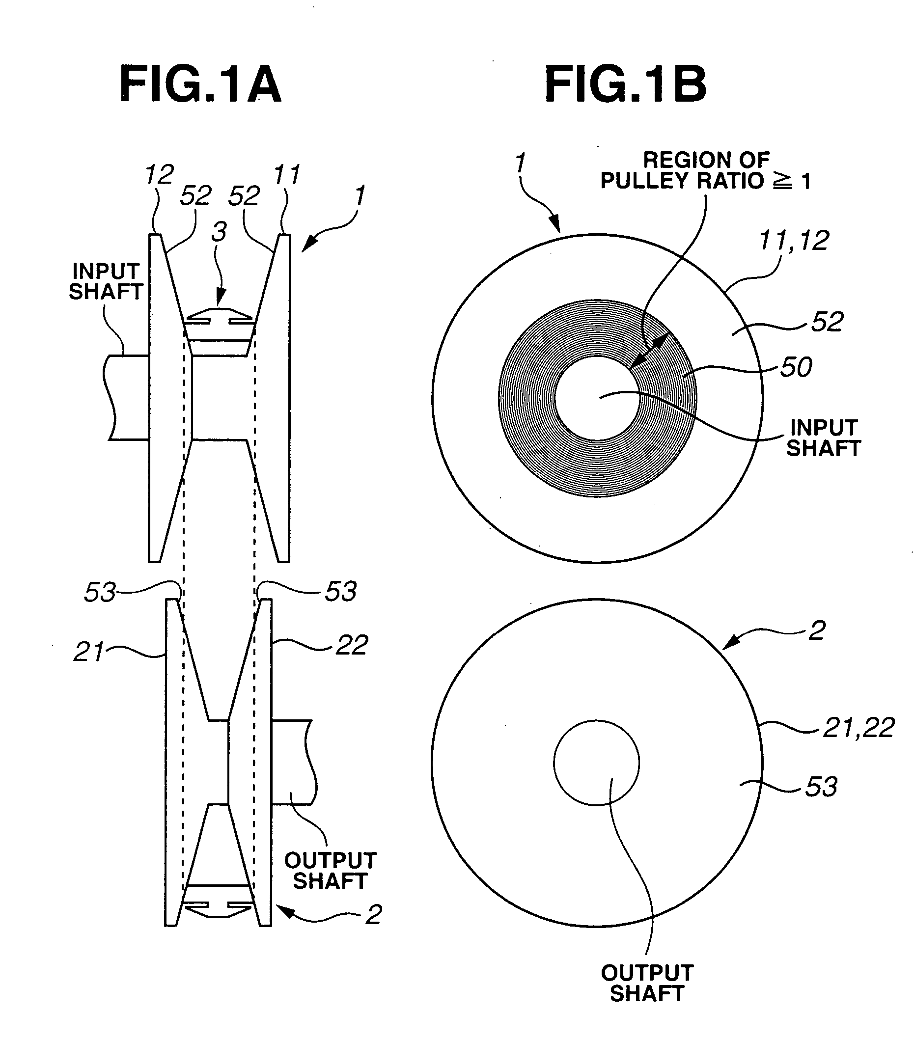
[0026] In the followings, embodiments of the present invention will be described with reference to the accompanying drawings. FIG. 1A schematically illustrates a relative arrangement of primary pulley 1, secondary pulley 2 and endless belt 3 of a continuously variable belt drive transmission (hereinafter referred to as a belt drive CVT). FIG. 1B illustrates primary pulley 1 on an input shaft and secondary pulley 2 on an output shaft as viewed in an axial direction of the input and output shafts. As illustrated in FIG. 1A, primary pulley 1 as an input pulley is constructed of stationary pulley half 11 formed integrally with the input shaft, and moveable pulley half 12 moveable in an axial direction of the input shaft. Similarly, secondary pulley 2 as an output pulley is constructed of stationary pulley half 21 formed integrally with the output shaft, and moveable pulley half 22 moveable in an axial direction of the output shaft. Endless belt 3 is fitted between primary and secondary ...


PUM

PropertyMeasurementUnit
height H1aaaaaaaaaa
friction coefficientaaaaaaaaaa
surface roughness Raaaaaaaaaaa

Abstract

A process for producing a pulley for a belt drive CVT, including subjecting tapered surfaces of a preform of at least one of input and output pulleys to surface hardening, subjecting the surface-hardened tapered surfaces of the preform to hard turning to form microgrooves radially spaced from one another thereon, between which microprojections are formed, and reducing a height of the microprojections. Alternatively, a process for producing a pulley for a belt drive CVT, including subjecting tapered surfaces of a preform of at least one of input and output pulleys to surface hardening, subjecting the surface-hardened tapered surfaces of the preform to shot peening, and subjecting the shot-peened tapered surfaces of the preform to finishing to form microgrooves having a substantially equal pitch thereon.

Description

BACKGROUND OF THE INVENTION [0001] The present invention relates to a continuously variable belt drive transmission, and more particularly to a process for producing a microstructure on a surface of a pulley which is contacted with a belt. [0002] It is known that pulleys for continuously variable belt drive transmissions are produced through sequential steps including case hardening of a raw steel plate, cutting, hot forging, removal of scales, machining (turning or drilling), carburizing, quenching and tempering, and grinding. In the conventional arts, the pulleys are ground after the carburizing or high-frequency quenching to improve a fatigue strength thereof. Japanese Patent Application First Publication No. 8-260125 describes such pulleys. SUMMARY OF THE INVENTION [0003] However, the conventional art has failed to enhance a friction coefficient of the surface of the pulley which is contacted with a belt. Further, conventionally, in the case where it is intended to produce a pul...

Claims


Application Information

Patent Timeline
Patent Type & Authority Applications(United States)
IPC IPC(8): B23B1/00B21C37/30B24B39/00B24B39/04F16H9/16F16H55/36F16H55/38F16H55/49
CPCB24B39/04Y10T29/49453Y10T29/49456Y10T29/47A47J47/06B65D85/70
Inventor YOSHIDA, MAKOTOKATOU, YOSHIAKIITO, YASUO
Owner JATCO LTD
Why Eureka
Try Eureka