Disposable blade cartridge utility knife

Active Publication Date: 2005-10-06
VOTOLATO LIVING TRUST DATED JUNE 1 1994 AS WHOLLY AMENDED THE
View PDF36 Cites 42 Cited by
  • Summary
  • Abstract
  • Description
  • Claims
  • Application Information

AI Technical Summary

Benefits of technology

[0005] It is a major object to provide an improved knife or cutter or slitting device of simple, low cost, compact, simple component con

Problems solved by technology

This results in the “dulled” blades ending up everywhere and contaminating everything from food to chemical batches to textile and clothing.
The raw blades also are a saf

Method used


Image

  • Disposable blade cartridge utility knife
  • Disposable blade cartridge utility knife
  • Disposable blade cartridge utility knife

Examples


Embodiment Construction

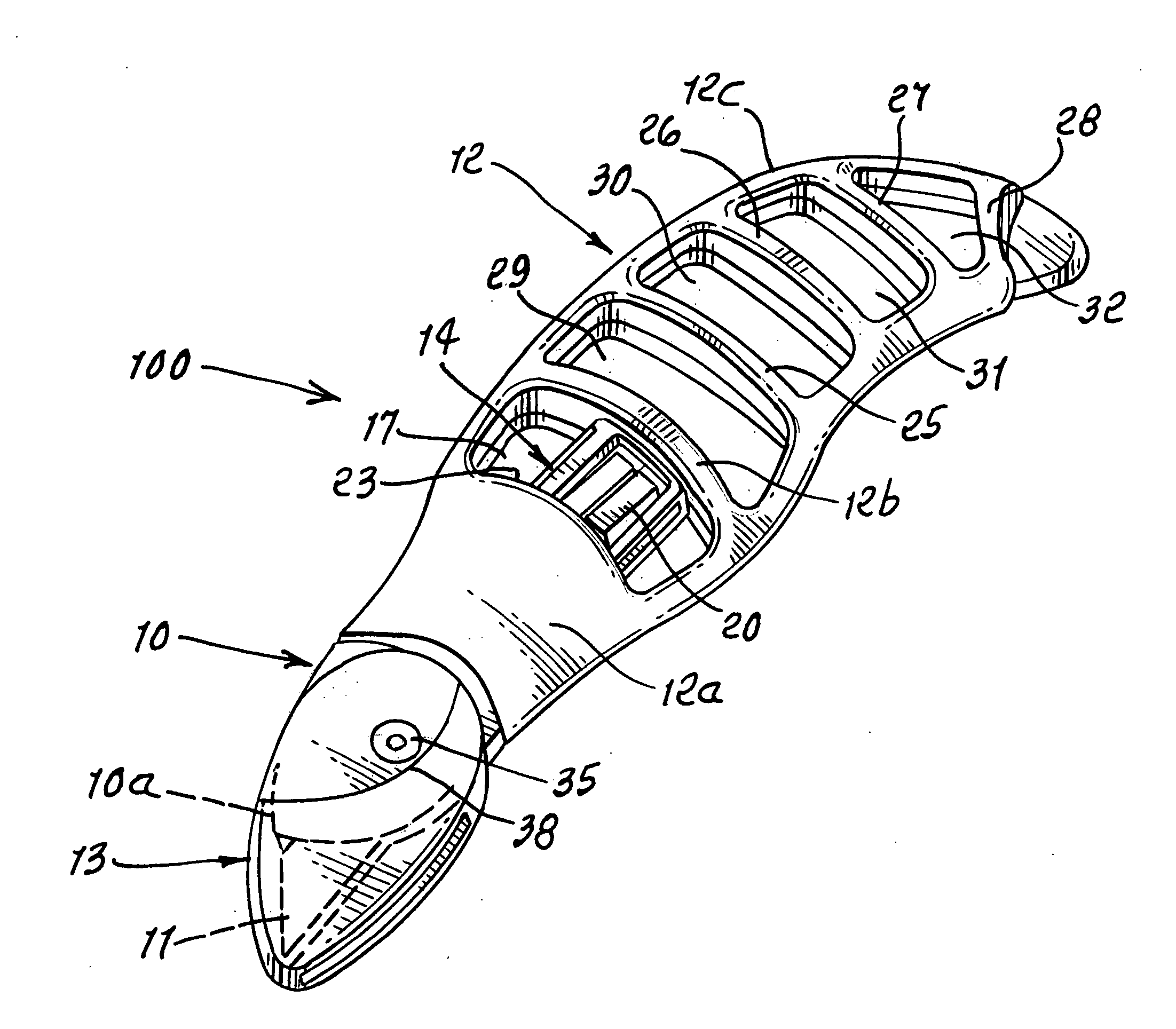
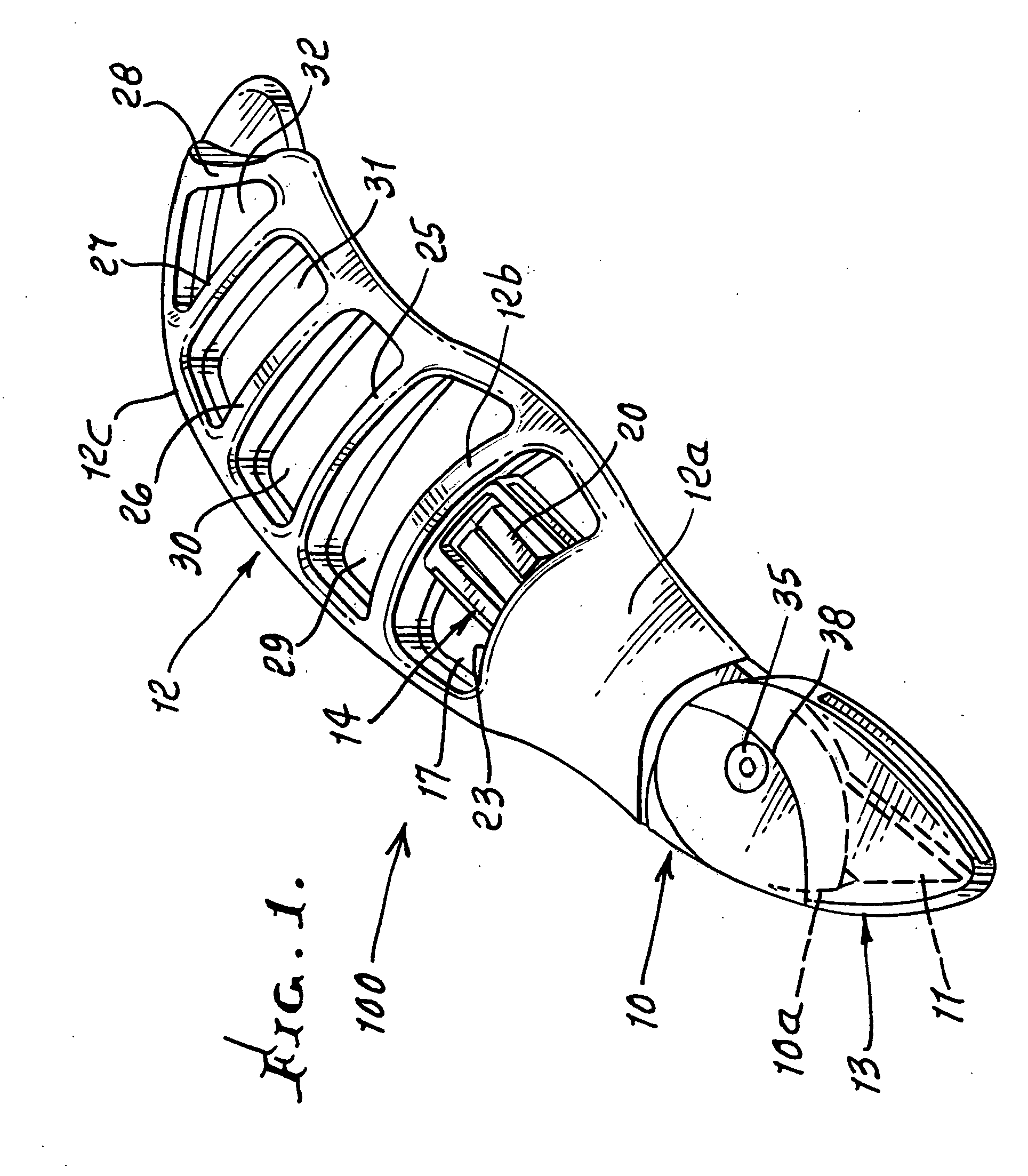
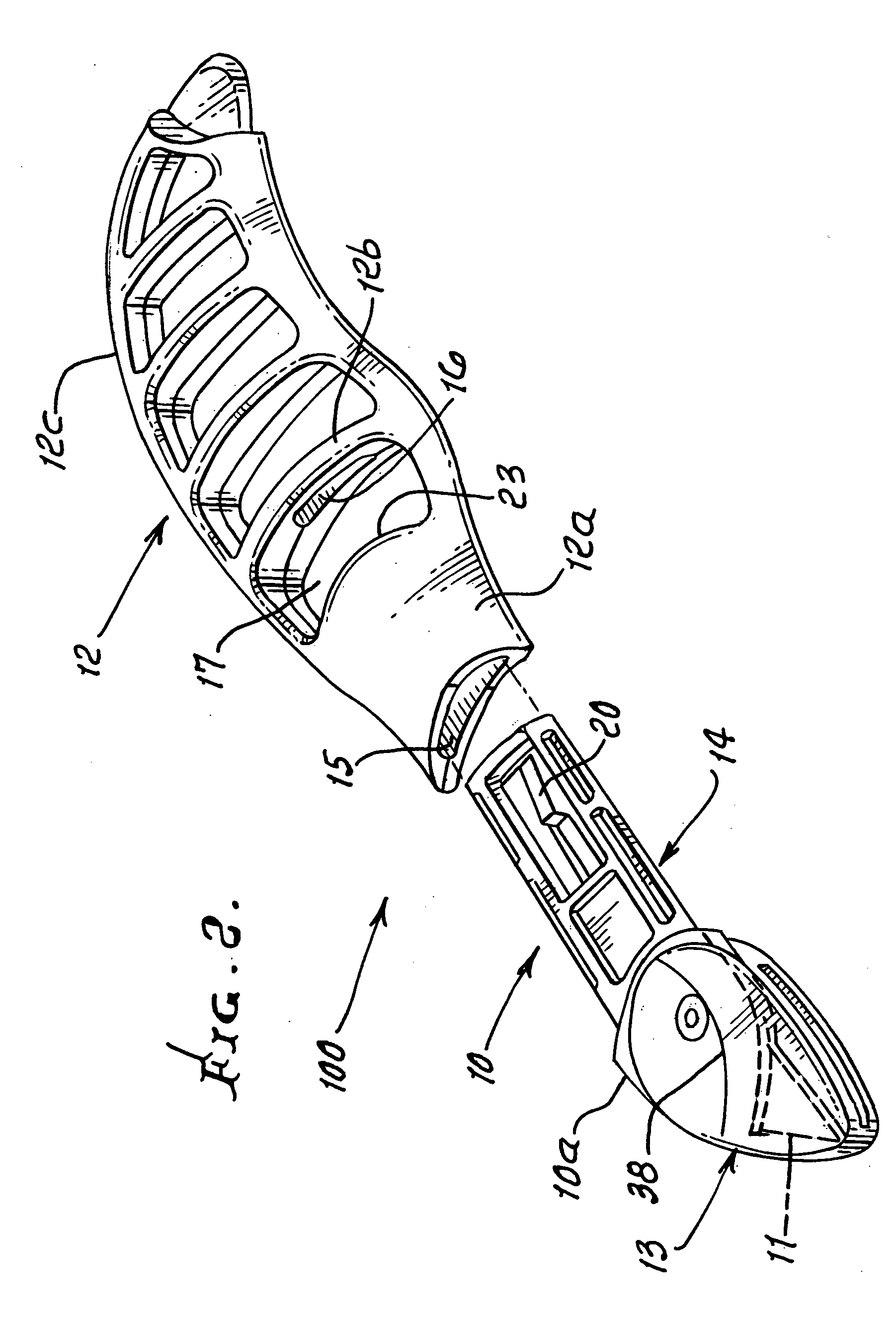
[0042] In the example, the knife 100 includes:

[0043] a) a cartridge, one example being shown at 10;

[0044] b) a blade carried by the cartridge body, one example of such a blade indicated at 11;

[0045] c) a holder supporting the cartridge so that the blade projects at 11a from the cartridge, one example of such a holder being indicated at 12; and

[0046] d) a shield for the blade, carried to be displaced relative to the holder to controllably expose the blade for cutting, one example of such a shield being shown at 13.

[0047] It will be understood that other forms of such elements 10-13 may be provided.

[0048] The illustrated cartridge 10 is configured to be receivable by the holder in such manner that it can be readily removable and replaced, thereby to enable blade replacement. The cartridge typically defines a blade carrying body portion 10a and a stem 14, shown in FIGS. 1, 3, 4 and 6-10. That stem is insertable endwise into the holder or handle 12 as via guide passages or slots 1...


PUM


Abstract

In a knife, the combination, comprising a cartridge, a blade carried by the cartridge, a holder supporting the cartridge so that the blade projects from the holder, a shield for the blade, carried to be displaced relative to the holder and blade to expose the blade, for cutting.

Description

BACKGROUND OF THE INVENTION [0001] This invention relates generally to cutting and / or slitting devices, as are used for opening boxes or cutting cardboard, and more particularly, to an improved device of simple, compact, heavy duty lightweight construction and enabling its throw-away disposal. [0002] Most utility knives are such that they require raw loose blades to be changed out when the blade dulls. This results in the “dulled” blades ending up everywhere and contaminating everything from food to chemical batches to textile and clothing. The raw blades also are a safety hazard even when disposed of in a trash receptacle due to someone having the job of rummaging through the trash looking for something they should not have thrown out. [0003] There is need for an improved utility knife that minimizes, if not eliminates such issues of safety and contamination. [0004] There is need for devices, as referred to above, and in particular, there is need for very low cost such devices whic...

Claims


Application Information

Patent Timeline
IPC IPC(8): B26B3/00B26B5/00B26B29/02
CPCB26B29/02B26B5/00
Inventor VOTOLATO, EARL
Owner VOTOLATO LIVING TRUST DATED JUNE 1 1994 AS WHOLLY AMENDED THE
Why Eureka
Try Eureka