Apparatus for powering an electronic musical instrument

a technology for electronic instruments and accessories, applied in the direction of electrophonic musical instruments, instruments, machines/engines, etc., can solve the problems of too often in a difficult to reach place in the instruments

Active Publication Date: 2005-10-06
IOFFE SIMONA
View PDF15 Cites 32 Cited by
  • Summary
  • Abstract
  • Description
  • Claims
  • Application Information

AI Technical Summary

Benefits of technology

[0010] The foregoing needs in the prior art are met by the present invention. Electrical power is externally provided to signal conditioner circuitry mounted inside musical instruments so the need to access the interior of such musical instruments to change or remove batteries is eliminated. Such external electrical power is provided to the signal conditioner circuitry mounted inside a musical instrument by using a conditioned signal output connector or jack mounted through the wall of the instrument, so no additional connectors or jacks are required.

Problems solved by technology

A big disadvantage to locating batteries inside stringed instruments is that when it is time to remove and / or replace the batteries they are too often in a hard to reach place in the instruments.

Method used


Image

  • Apparatus for powering an electronic musical instrument
  • Apparatus for powering an electronic musical instrument
  • Apparatus for powering an electronic musical instrument

Examples


first embodiment

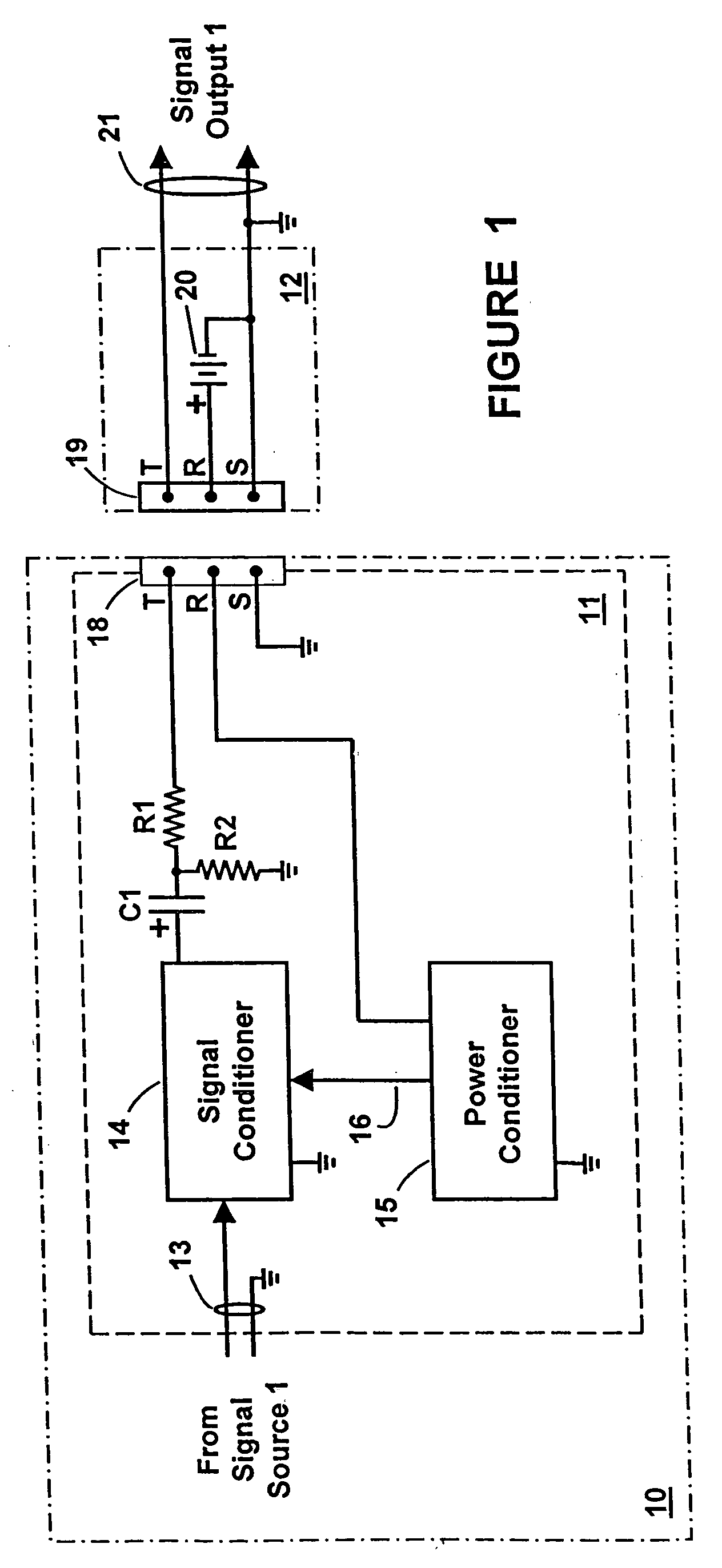
[0022] In FIG. 1 is shown a block diagram schematic of the invention wherein electronic circuitry including a signal conditioner 14 is located on a circuit board 11 on a musical instrument 10, but is powered by an electrical power source 20 that is external to the instrument. There is a jack 18 of the type described in the previous paragraph mounted on the musical instrument 10. There is also a plug 19 of the type described in the previous paragraph mounted on the end of a signal cable 21 that carries the conditioned signal to remote equipment such as an amplifier, soundboard or other audio equipment (not shown).

[0023] Briefly, the musical instrument 10 generates an electrical signal indicated as signal source 1 that is input to and processed by the signal conditioner 14 before being output from the instrument 10 via the jack 18. There is no source of electrical power mounted inside the instrument 10 for powering circuitry on the circuit board 11. The electronic circuitry mounted on...

third embodiment

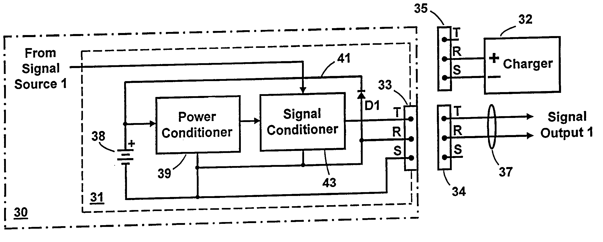
[0034] In FIG. 4 is shown a block diagram schematic of the invention where a power source 32 external to an instrument 30 is used to provide power to circuitry on circuit board 31 inside musical instrument 30. More particularly, the external power source 32 is used to charge an energy storage device 38, preferably in the form of a capacitor or a rechargeable battery, located on the musical instrument 30. The electronic circuitry on the board 31 is in turn powered by the charged rechargeable power source 38. Thus, the prior art need to frequently get inside instrument 30 to replace a non-rechargeable battery is eliminated.

[0035] With this configuration a main difference is that external power from charger 32 is not applied to instrument 30 while a plug 34 on the end of a signal cable 37 is plugged into a jack 33 to output the conditioned audio signal from musical instrument 30.

[0036] More particularly, to charge the rechargeable battery 38 inside instrument 30 a charger 32 with a pl...

fourth embodiment

[0040] In FIG. 5 is shown a block diagram schematic of the invention where an electrical power source 32 external to instrument 30 is used to provide electrical power to circuitry on circuit board 31 inside musical instrument 30. More particularly, as previously described with reference to FIG. 4, external power source 32 is used to charge an electrical energy storage device 38 which is preferably a capacitor or a rechargeable battery 38 that is located on the musical instrument 30. The electronic circuitry on circuit board 31 is, in turn, powered by the rechargeable power source 38. Thus, the prior art need to frequently get inside the instrument to remove or replace the battery is eliminated.

[0041] There are many similarities between the third and fourth embodiments of the invention, but there are some key differences. One similarity is that both embodiments utilize a charger 32 with a plug 35. Another similarity is that power conditioner 39 is a DC-DC converter that is utilized i...


PUM


Abstract

Apparatus for providing electrical power to signal conditioner circuitry inside a musical instrument having a signal output jack mounted thereon to carry a conditioned music signal via a signal cable to a remote location. The power source is a battery mounted inside a housing that is part of a signal plug on the signal cable plugged into the signal output jack. The battery powers the signal conditioner circuitry while the signal plug is in the jack. The housing provides access to the battery. Alternatively, a rechargeable power source is mounted inside or otherwise on the instrument and is connected to the jack. A power supply first plug is inserted into the signal output jack to charge the rechargeable power source. After charging the power source, the first plug is unplugged and a second plug of a signal cable is plugged into the jack to carry the conditioned signal to the remote location. When the second plug is plugged into the jack, the charged rechargeable power source provides power to the signal conditioner circuitry.

Description

CROSS REFERENCE TO RELATED APPLICATIONS [0001] This application claims the benefit of U.S. Provisional Patent Application Ser. No. 60 / 558,624, filed Apr. 1, 2004 by Simona Ioffe for SYSTEM FOR POWERING A S IGNAL CONDITIONER CIRCUIT DISPOSED INSIDE A CONCEALED VOLUME, and U.S. Provisional Patent Application Ser. No. 60 / 558,623, filed Apr. 1, 2004 by Simona Ioffe for SYSTEM FOR POWERING A SIGNAL CONDITIONER CIRCUIT DISPOSED INSIDE A CONCEALED VOLUME.BACKGROUND OF THE INVENTION [0002] 1. Field of the Invention [0003] This invention relates in general to means for supplying power to signal conditioner circuitry inside musical instruments. [0004] 2. Description of the Prior Art [0005] In the prior art, signal conditioner circuitry is often located inside musical instruments, such as stringed instruments. Such circuitry typically includes, but is not limited to, preamplifiers, buffers, equalizers and compressors. These circuits must have electrical power supplied thereto and energy source...

Claims


Application Information

Patent Timeline
Patent Type & Authority Applications(United States)
IPC IPC(8): G10H1/32G10H7/00H02J7/00H05F1/00
CPCG10H1/32H02J7/00G10H2230/035
Inventor IOFFE, SIMONA
Owner IOFFE SIMONA
Why Eureka
Try Eureka