Riflescope and the laser rangefinder used therein

a laser rangefinder and riflescope technology, applied in the field of riflescopes, can solve the problems of trouble for the shooter and difficulty in identification, and achieve the effect of improving productivity and significantly improving the shooting experien

Inactive Publication Date: 2005-10-06
ASIA OPTICAL CO INC
View PDF7 Cites 65 Cited by
  • Summary
  • Abstract
  • Description
  • Claims
  • Application Information

AI Technical Summary

Benefits of technology

[0012] The present invention is different from the prior art in that the reticle or aiming reference mark for the present riflescope is disposed at a distance of the second focal length so as to coincide with the second focal plane, and the image of data of the range displayed by the display panel is also projected on the second focal plane. This ensures that both the image of data of the range displayed by the display panel and the reticle size will not be affected by the erector lens, whereby...

Problems solved by technology

In contrast, when the magnification is decreased, as shown in FIG. 6, both the image of data of the range of the LED panel 86 and the reticle size are also ...

Method used


Image

  • Riflescope and the laser rangefinder used therein
  • Riflescope and the laser rangefinder used therein
  • Riflescope and the laser rangefinder used therein

Examples


Embodiment Construction

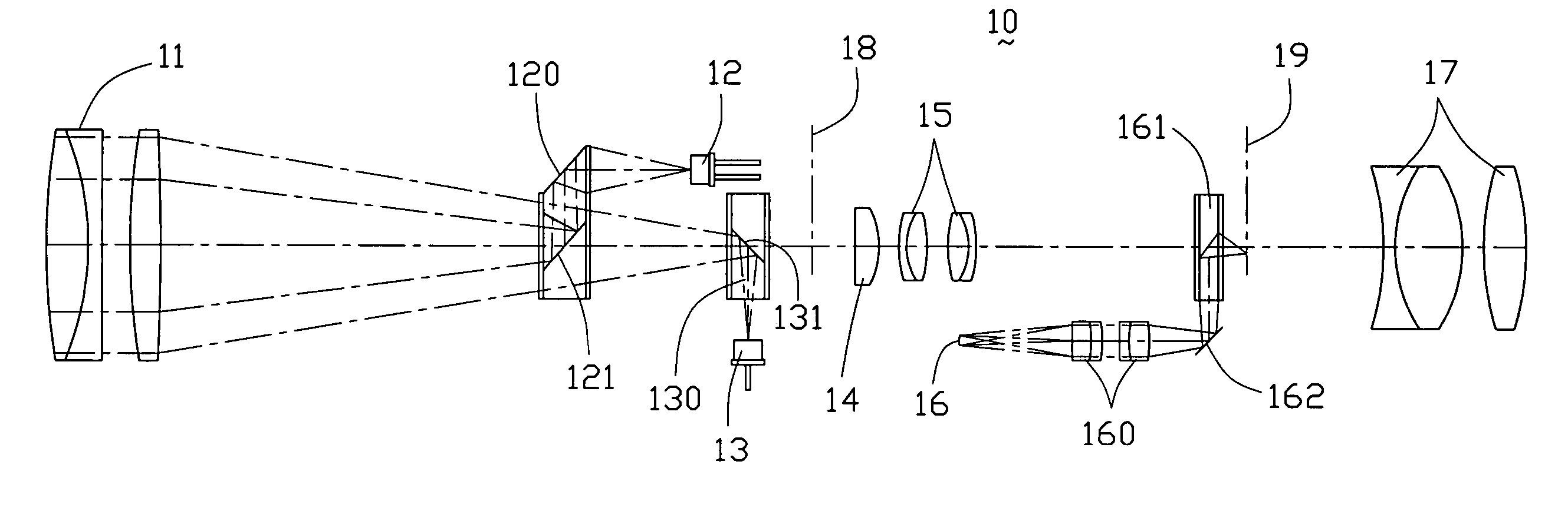
[0025] Referring to FIG. 7, a riflescope 10 in accordance with the present invention includes an objective element 11, a Laser Diode (LD) 12, an LD prism 120, an Avalanche Photoelectric Diode (APD) 13, an APD prism 130, a collector lens 14, an erector lens 15, a Light Emitting Diode (LED) panel 16, an LED lens element 160, an LED prism 161, a reticle and an eyepiece (ocular lens) element 17. The objective element 11, the eyepiece element 17, the erector lens 15 and the reticle together constitute a telescope system of the present riflescope 10. The objective element 11 has a first focal plane 18, wherein the distance from the objective element 11 to the first focal plane is defined as a first focal length. The eyepiece element 17 is aligned with the objective element 11 to define an optical axis of the optical system of the present riflescope 10. The eyepiece element 17 has a second focal plane 19, wherein the distance from the objective element 17 to the second focal plane is defin...


PUM


Abstract

An optical system for a riflescope (10) includes an objective element (11), an eyepiece element (17), an LD (12), an APD prism (130), an erector lens (15), an LED prism (160) and an LED panel (16). The erector lens is positioned between a first focal plane (18) and a second focal plane (19). The reticle is disposed at a distance of the second focal length so as to coincide with on the second focal plane. The LED prism is positioned between the erector lens and the second focal plane. The image of data of the range displayed by the LED panel is projected on the second focal plane through the LED prism. By this arrangement, the size and brightness of the reticle and the image of data of the range will not grow or shrink along with the target image size when the magnification is changed, and thus the shooter's vision feeling can be improved.

Description

BACKGROUND OF THE INVENTION [0001] 1. Field of the Invention [0002] The present invention relates to a riflescope, and particularly relates to a riflescope having the reticle coinciding with a second focal plane (eyepiece plane) thereof and the image of data of the range also projected to the second focal plane. [0003] 2. Description of Prior Art [0004] It is well known that a riflescope employs optics to provide a magnified view of the target aimed at and helps the shooter to distinguish a distant target from its background. Therefore, the riflescope is applicable to carry out precise shooting in the distant aim. As shown in FIG. 1, the optical system for a conventional riflescope 90 basically includes an objective element 91, an erector lens 92, an eyepiece (ocular lens) element 93 and a reticle 94 for facilitating aiming at the target. As the reticle 94 is disposed coinciding with a second focal plane (eyepiece plane) of the riflescope 90, the image of the reticle 94 will not be ...

Claims


Application Information

Patent Timeline
IPC IPC(8): F41G1/38G02B23/00G02B23/10
CPCF41G1/38G02B23/10F41G3/065
Inventor LIN, CHEN YEHYUNG, LIANG SHANG
Owner ASIA OPTICAL CO INC
Why Eureka
Try Eureka