
Inductive magnetic head with non-magnetic seed layer gap structure and method for the fabrication thereof

a non-magnetic, seed layer gap technology, applied in the field of magnetic heads, to achieve the effect of reducing sidewall redeposition, convenient electroplating of the p2 pole tip, and desirable magnetic flux flow characteristics

Inactive Publication Date: 2005-10-06
WESTERN DIGITAL TECH INC
View PDF14 Cites 9 Cited by
  • Summary
  • Abstract
  • Description
  • Claims
  • Application Information

AI Technical Summary

Benefits of technology

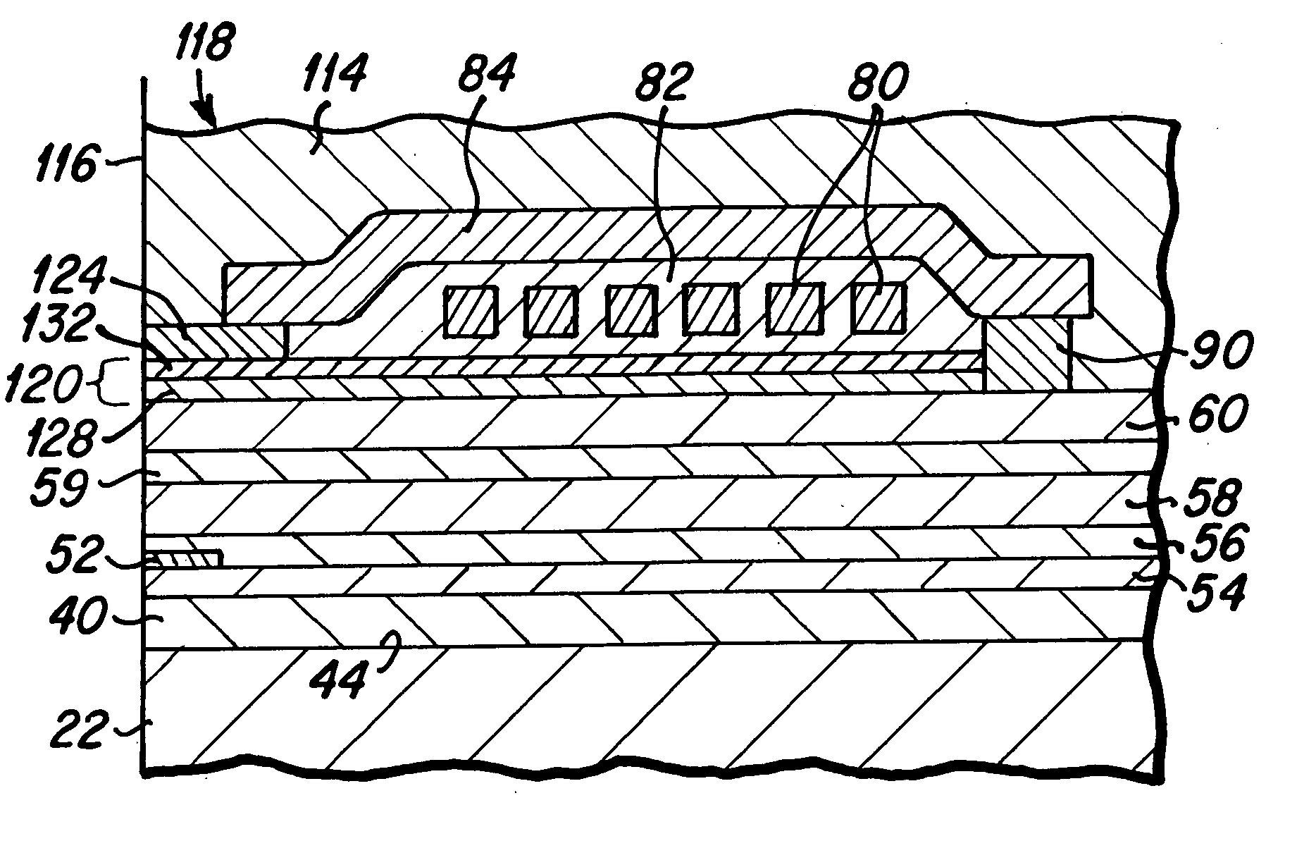
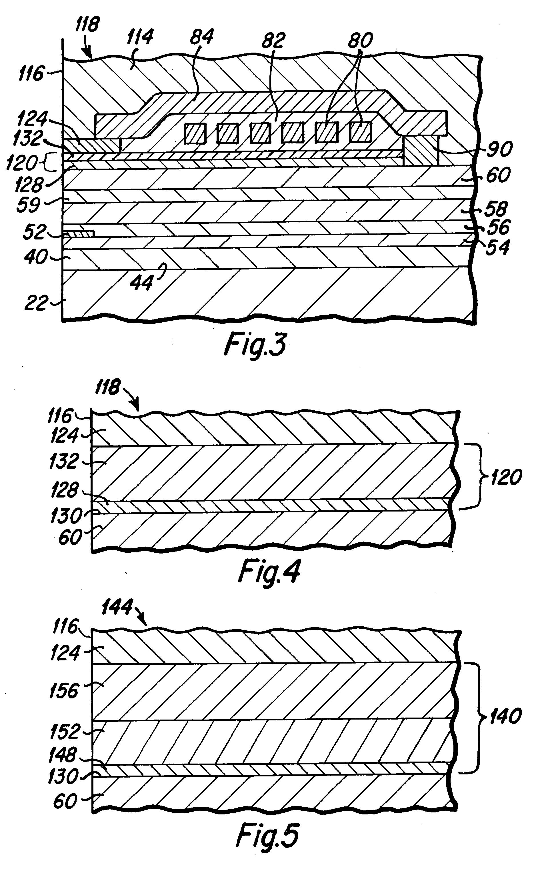
[0008] In an alternative embodiment the write gap layer includes another sublayer that is formed between the adhesion sublayer and the electrically conductive non-magnetic second sublayer. This third sublayer is comprised of a material that is etchable in a reactive ion etch (RIE) process, and the third sublayer is preferable comprised of Ta, Ti, W, Mo or Si, and is formed with a thickness of from approximately 100 Å to approximately 1,000 Å, with a preferred thickness of approximately 600 Å. Where the third sublayer is included, the electrically conductive, non-magnetic second sublayer is preferably formed with a thickness of from approximately 100 Å to approximately 1,000 Å, with a preferred thickness of approximately 200 Å. The third sublayer is useful where a P1 pole notching process is to be undertaken in the fabrication of the magnetic head. The utilization of the RIE etchable third sublayer during a P1 pole notching process utilizing a reactive ion species results in reduced redeposition of etched material upon the sides of the P2 pole tip as compared to prior art P1 pole notching processes. This can also reduce the overall process time to mill the pole tip.
[0014] It is a further advantage of the hard disk drive of the present invention that it includes a magnetic head having a write head element including a P2 magnetic pole tip having more desirable magnetic flux flow characteristics.

Problems solved by technology

In this situation, the relatively ordinary magnetic properties of the magnetic seed layer are detrimental to the desired magnetic flux flow through the P2 pole tip.

Method used


Image

  • Inductive magnetic head with non-magnetic seed layer gap structure and method for the fabrication thereof
  • Inductive magnetic head with non-magnetic seed layer gap structure and method for the fabrication thereof
  • Inductive magnetic head with non-magnetic seed layer gap structure and method for the fabrication thereof

Examples


Embodiment Construction

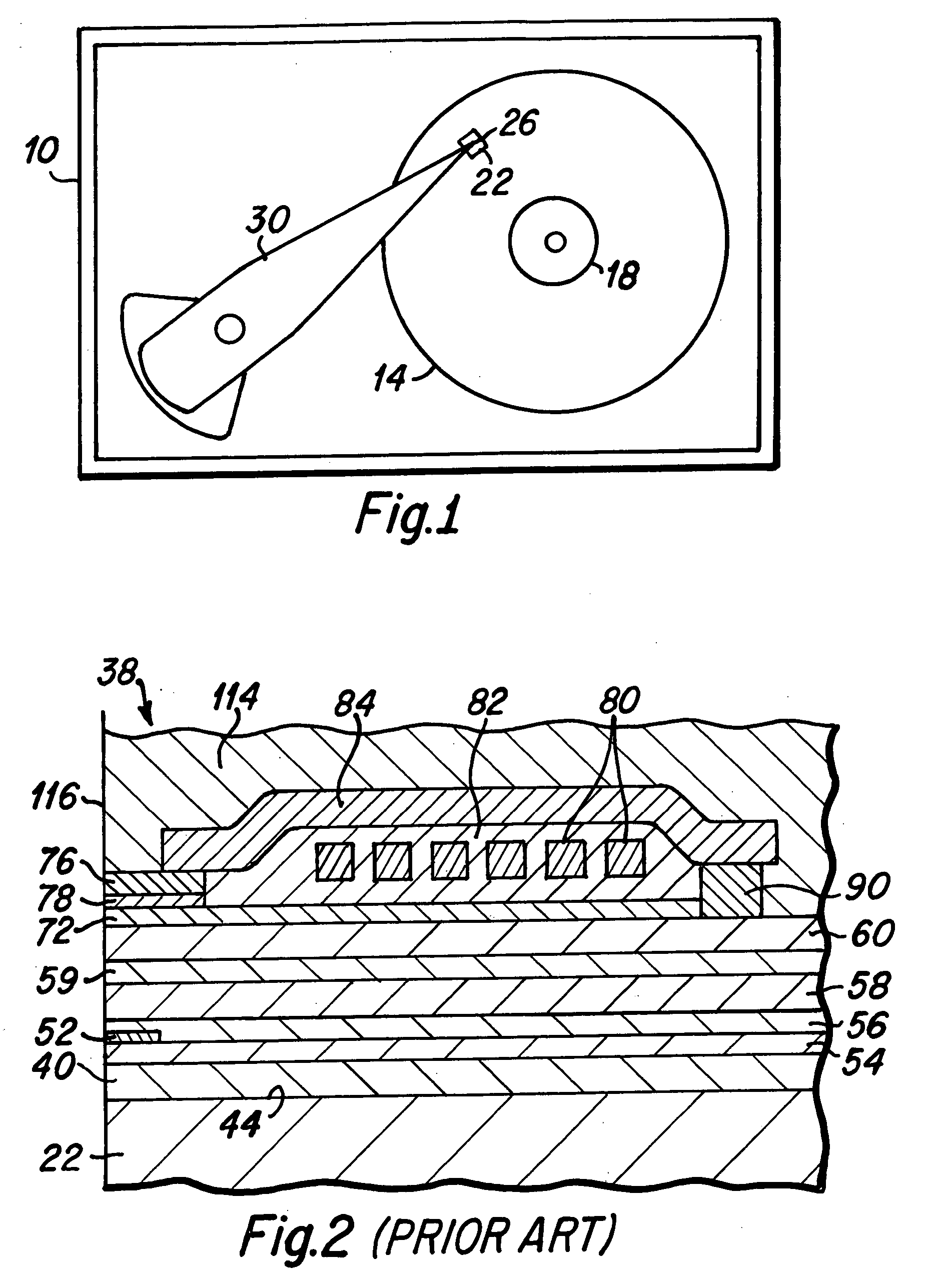
[0022] A simplified top plan view of a typical hard disk drive 10 which includes a magnetic head of the present invention is presented in FIG. 1. As depicted therein, at least one hard disk 14 is rotatably mounted upon a motorized spindle 18. A slider 22, having a magnetic head 26 disposed thereon, is mounted upon an actuator arm 30 to fly above the surface of each rotating hard disk 14, as is well known to those skilled in the art. The present invention includes improved features and manufacturing methods for such magnetic heads, and to better understand the present invention a prior art magnetic head is next described.

[0023] As will be understood by those skilled in the art, FIG. 2 is a side cross-sectional view that depicts portions of a prior art magnetic head 38, termed a longitudinal magnetic head. As is best seen in FIG. 2, the magnetic head 38 includes a first magnetic shield layer (S1) 40 that is formed upon a surface 44 of the slider body material 22. A read head sensor e...


PUM

PropertyMeasurementUnit
Thicknessaaaaaaaaaa
Electrical conductivityaaaaaaaaaa
Adhesion strengthaaaaaaaaaa

Abstract

A magnetic head including first and a second magnetic poles with a write gap layer disposed therebetween. In a first embodiment the write gap layer includes a non-magnetic, non-conductive first sublayer which is preferably comprised of Ta or Ti which is deposited upon the first magnetic pole to act as an adhesion layer. The write gap layer then includes a second sublayer which is formed of a non-magnetic, electrically conductive material which is preferably comprised of Rh or Ru. A P2 pole tip is electroplated upon the second sublayer, where the electrically conductive second sublayer is utilized to conduct electroplating current. In an alternative embodiment the write gap layer includes a third sublayer that is etchable in a reactive ion etch (RIE) process, and formed between the first and second sublayers. The third sublayer is preferably comprised of Ta or Ti.

Description

BACKGROUND OF THE INVENTION [0001] 1. Field of the Invention [0002] The present invention relates generally to magnetic heads for hard disk drives, and more particularly to the fabrication of a non-magnetic electrically conductive write gap structure between the magnetic poles of a write head portion of such magnetic head. [0003] 2. Description of the Prior Art [0004] As is well known to those skilled in the art, standard magnetic heads include write head elements that include two magnetic poles, commonly termed the first magnetic pole (P1) and the second magnetic pole (P2) poles, with a write gap layer formed between them. During a data recording procedure, the passage of magnetic flux across the write gap between the two poles creates a magnetic field which influences a thin film layer of magnetic media on a hard disk that is located proximate the magnetic head, such that the changing magnetic flux creates data bits within the magnetic media. In a longitudinal magnetic head the si...

Claims


Application Information

Patent Timeline
IPC IPC(8): G11B5/147G11B5/187G11B5/23G11B5/235G11B5/31
CPCG11B5/187G11B5/235Y10T29/49046G11B5/313G11B5/3116
Inventor HIXSON-GOLDSMITH, APRIL DAWNLILLE, JEFFREY S.
Owner WESTERN DIGITAL TECH INC
Learn More