Method for detecting output current of inverter and device therefor

a technology of inverter and output current, which is applied in the direction of dc-ac conversion without reversal, fault location, instruments, etc., can solve the problem of increasing the difficulty of detecting output voltage vo using a low-performance cpu or dsp, and the magnitude of this error, so as to achieve the effect of easy calculation of output curren

Inactive Publication Date: 2005-10-06
SANYO DENKI CO LTD
View PDF7 Cites 14 Cited by
  • Summary
  • Abstract
  • Description
  • Claims
  • Application Information

AI Technical Summary

Benefits of technology

[0007] With this invention, the output voltage vo is detected for obtaining its effective value or average value V. A cosine wave digital data [hereinafter referred to as cos Wave Data is obtained by advancing by 90 degrees a phase of an inverter sine wave data used ot obtain the output voltage vo. The cos WaveData may be obtained in advance and stored in a memory means. Then, in this invention, a current ic′ equivalent to the capacitor current ic is digitally calculated by the following expression. ic′=V×ω0×C×[cos WaveData]×K where C is a capacitance of the capacitor C and ω0 is an angular frequency of the output voltage. The angular frequency ω0 can be obtained by calculating depending on the output voltage or stored in a memory means in advance. In the above expression, K is a value obtained by multiplying a detection ratio for detecting the output voltage vo, a conversion ratio for converting an analog value to a digital value and a conversion ratio for converting the effective value or average value V into a maximum value. The current ic′ thus obtained is used to calculate an output current io=iL−ic′ by taking the current ic′ as the capacitor current ic. Since the above expression can be calculated by multiplication alone, the calculation can be performed easily even by a low-performance CPU or DSP. There is no problem of degraded calculation accuracy.
[0009] With this invention, since a current equivalent to the capacitor current can be calculated in real time by multiplication operations alone, the output current can be calculated easily even with a low-performance CPU or DSP without degrading a calculation accuracy.

Problems solved by technology

But as the magnitude of the capacitor current ic becomes closer to that of the output current io, not only the magnitude of this error but also the adverse effect of the error increase.
However, differentiating the output voltage vo using a low-performance CPU or DSP is technically difficult.

Method used


Image

  • Method for detecting output current of inverter and device therefor
  • Method for detecting output current of inverter and device therefor

Examples


Embodiment Construction

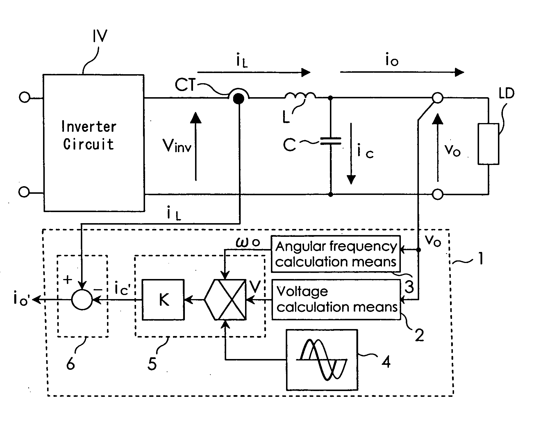
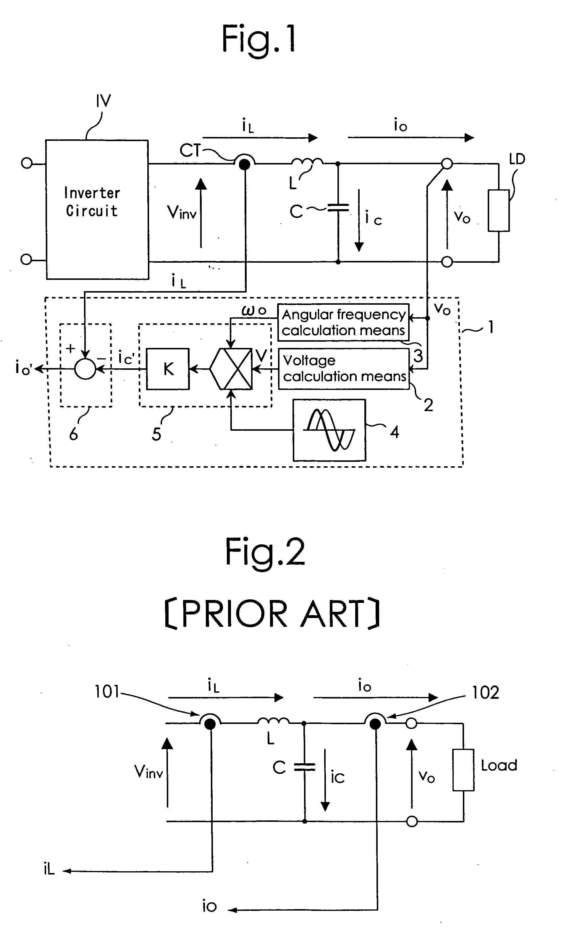
[0012] By referring to the accompanying drawings, an example embodiment of an output current detection device that implements an inverter output current detection method of this invention will be described. An embodiment of the inverter output current detection method will also be explained. FIG. 1 shows an example configuration of an output current detection device according to this invention. As with the conventional device of FIG. 2, the embodiment of this invention has at the output side of an inverter circuit IV an LC filter made up of a reactor L and a capacitor C. A reactor current iL flowing through the reactor L is detected by a current transformer CT. A voltage across the capacitor C is supplied to a load LD as an output voltage vo. Reference number 1 represents an output current detection device that calculates an output current io by subtracting a current ic′ equivalent to a capacitor current ic flowing through the capacitor C from the reactor current iL in the inverter....


PUM


Abstract

An inverter output current detection device is provided which can calculate an output current of an inverter easily by using a low-performance calculating device without lowering a calculation accuracy. A current ic′ equivalent to a capacitor current ic is digitally calculated according to a predetermined expression. This expression is ic′=V×ω0×C×[cos Wavedata]×K, where V is an effective value or average value of an output voltage vo, C is a capacitance of a capacitor C, ω0 is an angular frequency of the output voltage, and K is a value obtained by multiplying a detection ratio for detecting the output voltage vo, a conversion ratio for converting an analog value into a digital value, and a conversion ratio for converting the effective value or average value V into a maximum value.

Description

BACKGROUND OF THE INVENTION [0001] The present invention relates to a method and a device for detecting an output current of an inverter by calculation therefor. [0002]FIG. 2 shows an example of an output circuit in a conventional inverter. Generally, an output of an inverter circuit used in an uninterruptible power supply is filtered by an LC filter made up of a reactor L and a capacitor C before being output. A control of the inverter requires a detection of an output current iL of the inverter circuit. For this purpose a current detector is provided at a position 101 in FIG. 2. When there is a need to detect an output current (load current) io of the inverter, a current detector is provided at a position 102 in FIG. 2. [0003] When both of the output current iL of the inverter circuit and the load current io of the inverter need to be detected, two detectors are required. For a reduction of size and cost, some inverters use the output current iL of the inverter circuit rather than...

Claims


Application Information

Patent Timeline
Patent Type & Authority Applications(United States)
IPC IPC(8): H02M7/48H02M7/537
CPCH02M7/53873H02M7/537
Inventor NAGAI, MASAHIKOHANAOKA, HIROYUKI
Owner SANYO DENKI CO LTD
Why Eureka
Try Eureka