
Circuit for synchronizing symbols of OFDM signal

a synchronizing circuit and symbol technology, applied in the field of symbols synchronizing circuits for synchronizing symbols of received signals, can solve the problems of large fluctuation in received electric power, large noise, and inability to detect symbols with fixed thresholds, and achieve high-quality symbol timing detection.

Inactive Publication Date: 2005-10-06
FUJITSU LTD
View PDF5 Cites 50 Cited by
  • Summary
  • Abstract
  • Description
  • Claims
  • Application Information

AI Technical Summary

Benefits of technology

[0022] According to at least one embodiment of the invention, thresholds are changed in response to the received electric power when detecting the timing of OFDM symbols by checking the levels of a synchronous summation and at least one of a moving average and an autocorrelation electric power. Namely, the thresholds dynamically adjusted in response to the received electric power are used for checking the levels of signals that are different from the received electric power. This makes it possible to achieve highly accurate detection of symbol timing even if the received electric power fluctuates due to a noise created by the influence of multi-paths or the like.

Problems solved by technology

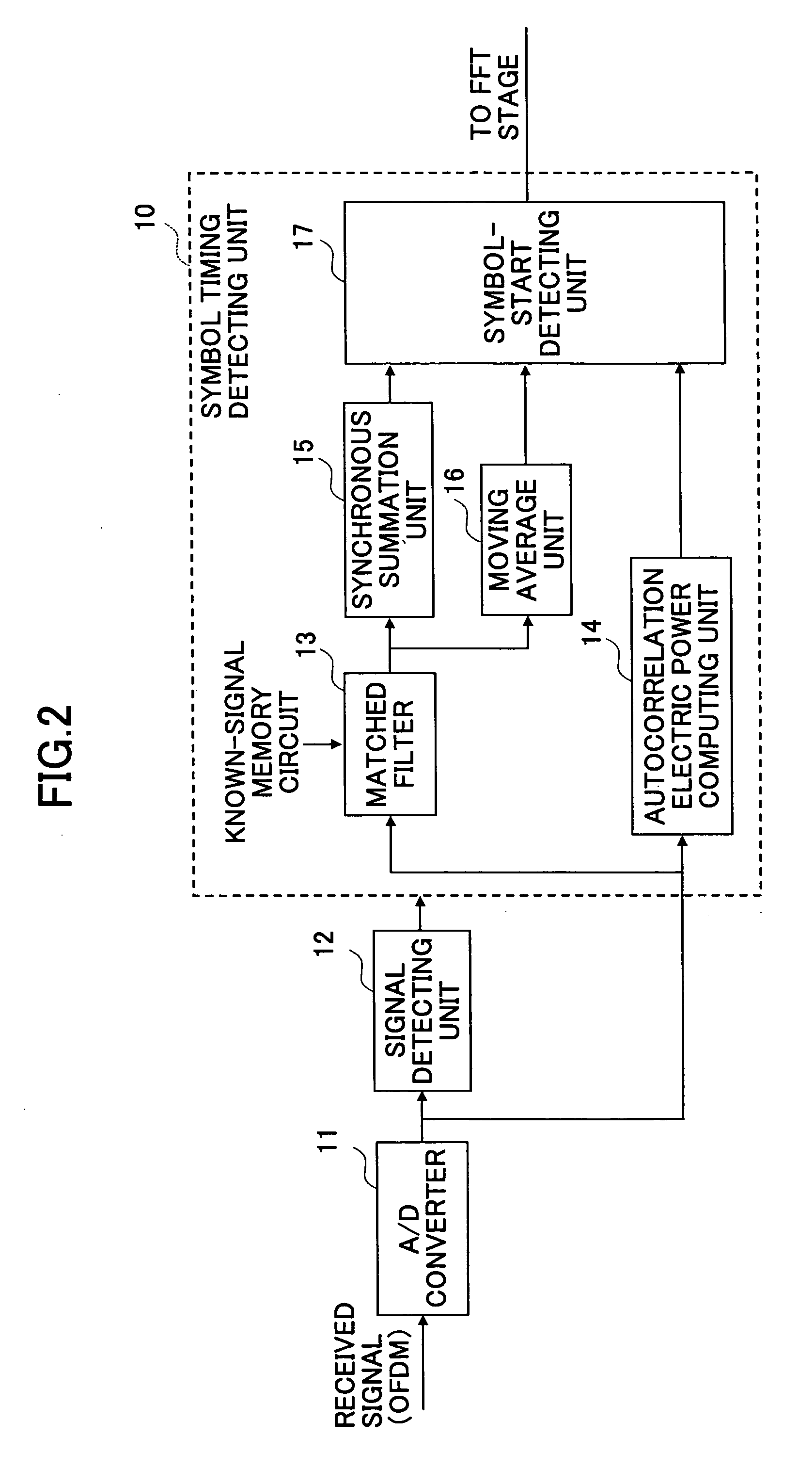
The related-art construction shown in FIG. 2 has a drawback in that it is sensitive to noise because fixed thresholds are used for the checking of levels of synchronous summations, autocorrelation electric powers, and moving averages.
The synchronous detection of symbols by use of fixed thresholds suffers a significant drop in accuracy, especially in a multi-path configuration where multi-path delay waves are superimposed on a received signal, thereby creating large fluctuation in received electric power.
This technology, however, is only directed to the threshold-based checking of signal electric power, and is silent about synchronous detection based on other signals.

Method used


Image

  • Circuit for synchronizing symbols of OFDM signal
  • Circuit for synchronizing symbols of OFDM signal
  • Circuit for synchronizing symbols of OFDM signal

Examples


first embodiment

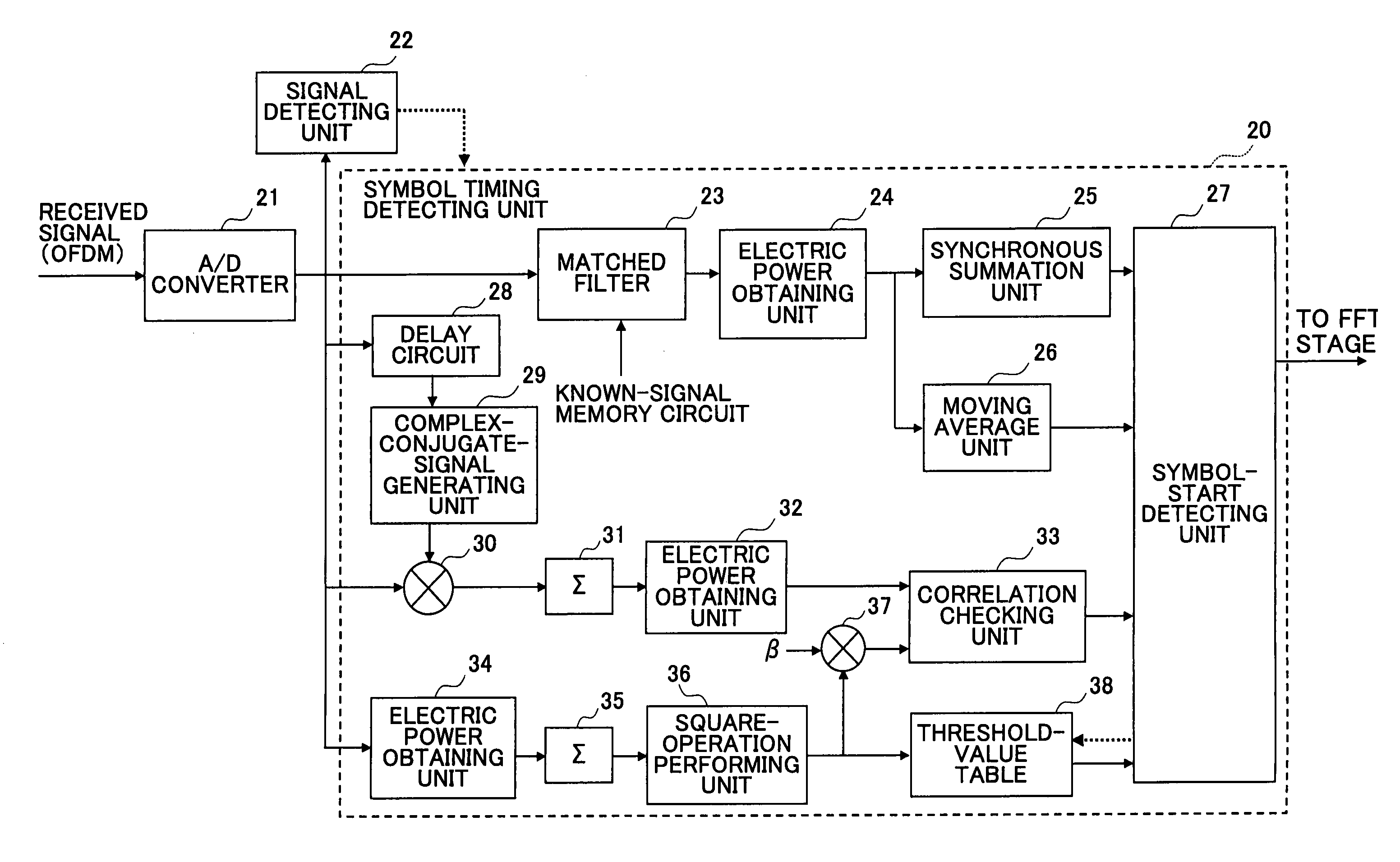
[0036]FIG. 3 is a block diagram showing an apparatus for detecting symbol timing according to the invention. The construction shown in FIG. 3 includes a symbol timing detecting unit 20, an A / D converter 21, and a signal detecting unit 22. The symbol timing detecting unit 20 includes a matched filter 23, an electric power obtaining unit 24, a synchronous summation unit 25, a moving average unit 26, a symbol-start detecting unit 27, a delay circuit 28, a complex-conjugate-signal generating unit 29, a complex-number multiplying unit 30, an integrating unit 31, an electric power obtaining unit 32, a correlation checking unit 33, an electric power obtaining unit 34, an integrating unit 35, and a square-operation performing unit 36, a coefficient multiplying unit 37, and a threshold-value table 38. The A / D converter 21 performs A / D conversion on the received OFDM signal for provision to the signal detecting unit 22, the matched filter 23, the delay circuit 28, the complex-conjugate-signal...

second embodiment

[0059] The second embodiment as described above achieves sharing of a common circuit portion between the signal detecting unit 22 for packet detection and the symbol timing detecting unit 20 for symbol timing detection, thereby reducing circuit size and power consumption. Moreover, the same advantage is provided for the AGC control unit.

third embodiment

[0060]FIG. 9 is a block diagram showing the symbol timing detecting apparatus according to the invention. In FIG. 9, the same elements as those of FIG. 8 are referred to by the same numerals, and a description thereof will be omitted.

[0061] In the OFDM, an autocorrelation value is used in the estimation of an offset of broadband carrier frequencies. The third embodiment shown in FIG. 9 achieves sharing of a circuit portion for computing an autocorrelation value between the signal detecting unit 22 of the second embodiment and a broadband-carrier-frequency-offset estimating unit. In the construction shown in FIG. 9, the broadband-carrier-frequency-offset estimating unit includes a buffer 51 and a phase computing unit 52. After packet detection, the autocorrelation value output from the integrating unit 31 of the signal detecting unit 22 is supplied to the buffer 51 concurrently with the activation of AGC control and a symbol timing detecting operation. After the symbol timing detecti...


PUM


Abstract

A circuit for synchronizing symbols of a received OFDM signal includes a cross-correlation detecting unit configured to detect cross-correlation of a received signal to generate a value of the cross-correlation, a synchronous summation unit configured to obtain synchronous summation of the value of the cross-correlation performed at predetermined intervals, a received electric power obtaining unit configured to obtain received electric power of the received signal, an autocorrelation electric power obtaining unit configured to obtain autocorrelation electric power of the received signal, a threshold obtaining unit configured to obtain a synchronous summation threshold responsive to the received electric power, and a symbol timing detecting unit configured to identify timing of a peak of the synchronous summation as symbol timing in response to detecting, at the timing of the peak, that the autocorrelation electric power is smaller than the received electric power multiplied by a predetermined factor and that the synchronous summation is larger than the synchronous summation threshold.

Description

CROSS-REFERENCE TO RELATED APPLICATIONS [0001] The present application is based upon and claims the benefit of priority from the prior Japanese Patent Application No. 2004-105974 filed on Mar. 31, 2004, with the Japanese Patent Office, the entire contents of which are incorporated herein by reference. BACKGROUND OF THE INVENTION [0002] 1. Field of the Invention [0003] The present invention generally relates to symbol synchronizing circuits for synchronizing symbols of received signals, and particularly relates to a symbol synchronizing circuit for synchronizing symbols of received OFDM signals. [0004] 2. Description of the Related Art [0005] In the OFDM (orthogonal frequency division multiplex) transmission, carrier waves that are arranged at constant frequency intervals and orthogonal to each other are subjected to digital modulation at symbol frequency, thereby achieving the allocation of data. Modulation and demodulation in the OFDM are achieved by performing the IFFT with respec...

Claims


Application Information

Patent Timeline
IPC IPC(8): H04B1/69H04L27/26
CPCH04L27/2665H04L27/2662
Inventor ZHOU, LIANG
Owner FUJITSU LTD
Learn More