
Methods for achieving high resolution microfluoroscopy

a microfluoroscopy and high resolution technology, applied in the field of high resolution microfluoroscopy, can solve the problems of limited spatial resolution, electron microscopy, saturation and nonlinear response of contact techniques, etc., and achieve the effect of improving resolution

Inactive Publication Date: 2005-10-06
HIRSCH GREGORY
View PDF8 Cites 27 Cited by
  • Summary
  • Abstract
  • Description
  • Claims
  • Application Information

AI Technical Summary

Benefits of technology

[0019] A resolution slightly below 150 nm is possible with a microfluoroscope using an oil immersion objective (NA=1.4) and a fluorescent screen with an emission wavelength at the lower end of the visible range. The technology disclosed here using e...

Problems solved by technology

While light microscopy is an ideal tool in most respects, its utility is constrained by its limited spatial resolution.
Electron microscopy, while stunningly successful in elucidating cell ultrastructure, has its own limitations.
The contact technique suffers from saturation and nonlinear response in the photoresist.
Obviously, the method is not real-time due to the separate exposure and development steps.
These instruments are very complex due to the elaborate electron optics that are required, and have not yet produced images with a resolution better than light microscopy.
The resolution of any contact microscopy method is limited by Fresnel diffraction in the contact image.
The resolution of the microfluoroscope is limited by the diffraction constraints of the objective lens used to view the image.
Unfortunately, such electron impact sources produce very low intensity in the soft x-ray range.
This leads to extremely long exposure times. Fortunately, much higher-intensity sources have been developed.
While synchrotron radiation is an ideal for soft x-ray microscopy, it is obviously not suitable for general use in small laboratories.
Radiation damage is a concern in all x-ray microscopy methods.

Method used


Image

  • Methods for achieving high resolution microfluoroscopy
  • Methods for achieving high resolution microfluoroscopy
  • Methods for achieving high resolution microfluoroscopy

Examples


Embodiment Construction

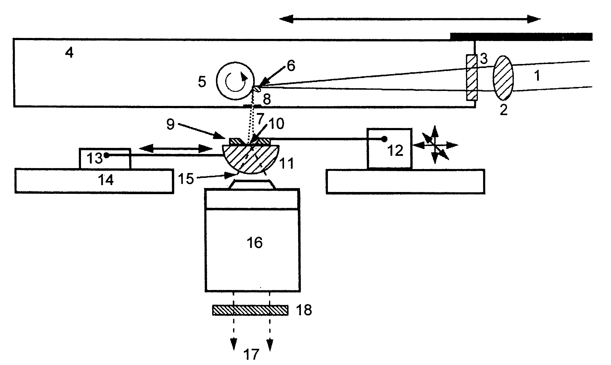
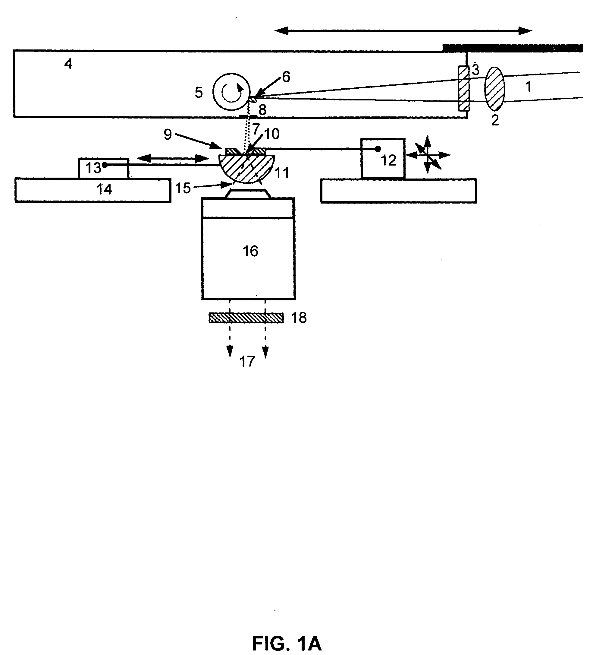
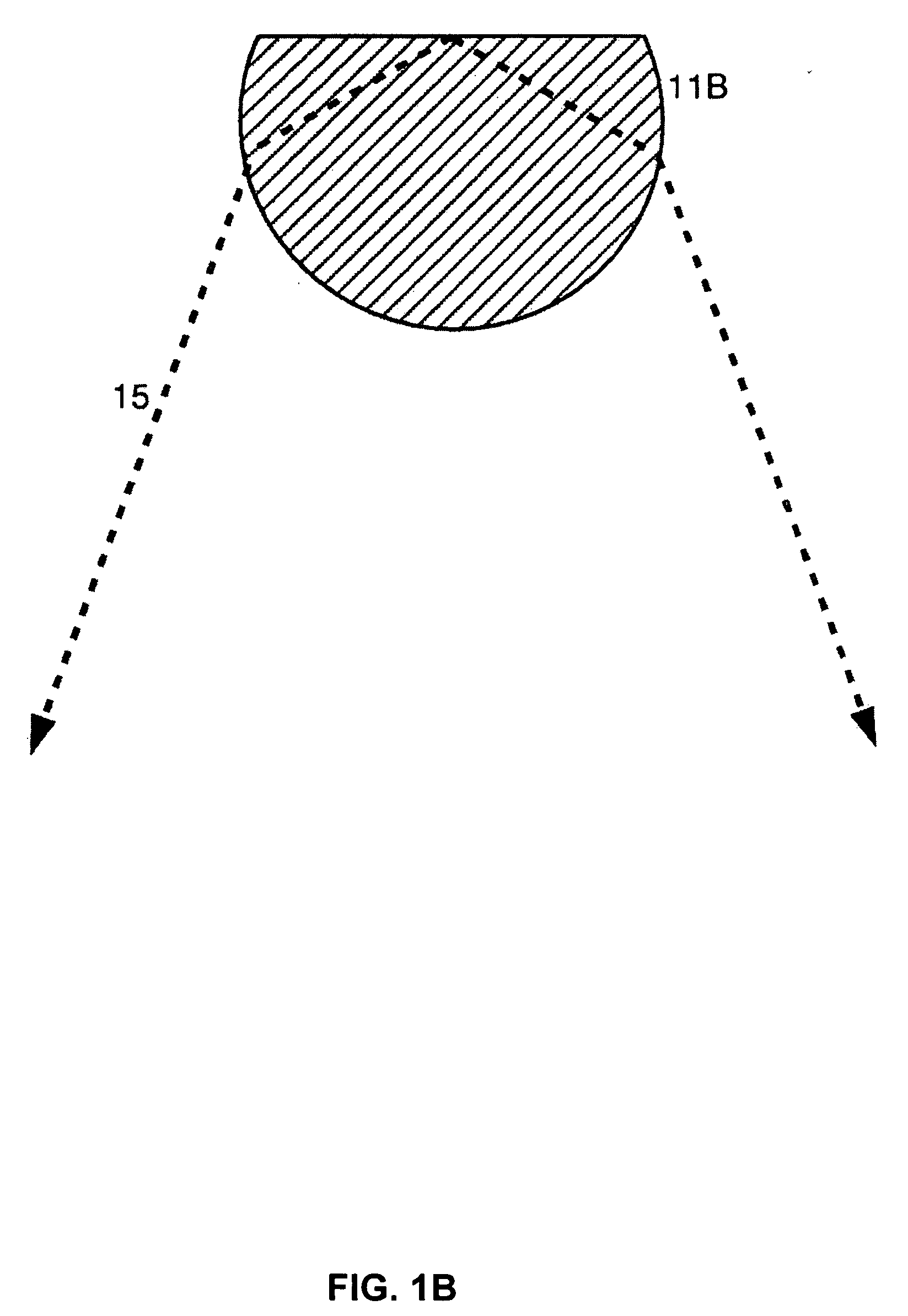
[0032] Two potential methods to push the resolution limit of the current instrument into the range of 0.1 μm and below are disclosed here. [0033] 1) Recently developed Solid Immersion Lens (SIL) technology is introduced into the light microscope's optics. Such lenses achieve an extremely high Numerical-Aperture (NA), permitting maximum resolution. In parallel with realizing the highest possible NA, the shortest practical emission wavelength for the fluoroscopic medium can also be used to attain the highest resolution. The solid immersion lens functions both as a high-resolution optical element, and as the scintillator of the microfluoroscope. [0034] 2) A scanning method is incorporated into the microfluoroscope to greatly improve the resolution. This approach relies on the use of an innovative nanochannel mask. The scanning procedure permits a resolution that is several times smaller than obtainable with any far-field optical microscope. This scanning method may also be found advant...


PUM


Abstract

A microfluoroscope has a source of soft x-rays and a solid immersion lens including a plano surface. There is means for placing a sample in close proximity to the plano surface so that an x-ray absorption shadowgraph of the sample is projected onto the plano surface by the source of soft x-rays. A scintillator on the solid immersion lens plano surface produces fluorescent light from soft x-rays passing through the sample. An optical microscope is used for viewing through the solid immersion lens the fluorescent light from the scintillator corresponding to the x-ray absorption shadowgraph of the sample. A microfluoroscope is also disclosed which includes a source of soft x-rays, a fluorescent screen placed at a plane to receive x-rays and means for placing a sample in close proximity to the plane so that an x-ray absorption shadowgraph of the sample is projected onto the fluorescent screen. A nanochannel mask placed between the fluorescent screen and the sample for limiting x-rays reaching the fluorescent screen to a periodic matrix of nanochanneled beams. A computer system combines all the discrete images at each raster position into a composite image representing the x-ray absorption shadowgraph of the entire sample.

Description

CROSS-REFERENCES TO RELATED APPLICATIONS [0001] This application claims the benefit of Provisional Patent Application 60 / 558,394 filed Mar. 31, 2004 entitled “Methods for Achieving Extremely High Resolution Microfluoroscopy.”GOVERNMENT RIGHTS IN THE INVENTION [0002] This invention was made under government support under Grant R44 GM62067 awarded by the National Institute of General Medical Sciences / National Institutes of Health. The United States Government as represented by the Secretary of Health and Human Services has certain rights in this inventionREFERENCE TO A “SEQUENCE LISTING,” A TABLE, OR A COMPUTER PROGRAM LISTING APPENDIX SUBMITTED ON A COMPACT DISK. [0003] NOT APPLICABLE [0004] The subject of this invention involves microfluoroscopy. More particularly, several methods aimed at achieving the highest possible spatial resolution in soft x-ray microfluoroscopy are disclosed. Although these methods could be applied to several different microfluoroscope configurations and typ...

Claims


Application Information

Patent Timeline
IPC IPC(8): G21K7/00
CPCG21K7/00
Inventor HIRSCH, GREGORY
Owner HIRSCH GREGORY
Learn More