System for automobile exhaust gas purification

a technology for automobile exhaust and purification system, which is applied in the direction of exhaust treatment electric control, separation process, human health protection, etc., can solve the problems of exhaust gas purification system, durability and heat resistance largely affected, and exhaust gas has a lot of harmful gases, so as to improve heat resistance and durability of ccc catalyst, the effect of reducing manufacturing cos

Inactive Publication Date: 2005-10-06
HYUNDAI MOTOR CO LTD
View PDF9 Cites 46 Cited by
  • Summary
  • Abstract
  • Description
  • Claims
  • Application Information

AI Technical Summary

Benefits of technology

[0013] The present invention provides a system to purify automobile exhaust gases capable of allowing an absorption catalyst to purify exhaust gases, where the exhaust gases flow through the absorption catalyst in a CCC at the initial start time of the engine and, afterward, a UCC catalyst to purify exhaust gases normally by flowing the exhaust gas only through the UCC catalyst by disconnecting a flow path connected with the absorption catalyst in the CCC during a warm-up state of the UCC catalyst. A HC absorption catalyst and a NOx absorption catalyst, each h

Problems solved by technology

The exhaust gas has a lot of harmful gases, such as CO, NOx, HC, etc.
However, the conventional exhaust gas purification system has the following problems.
First, in the case when the catalyst is positioned near the engine like the CCC, the durability and heat resistance are largely negatively affected.
In the case of Electrically Heated Catalyst (EHC) or Burner Heated Cataly

Method used


Image

  • System for automobile exhaust gas purification
  • System for automobile exhaust gas purification
  • System for automobile exhaust gas purification

Examples


Embodiment Construction

[0021] The preferred embodiments of the present invention will be described with reference to the accompanying drawings.

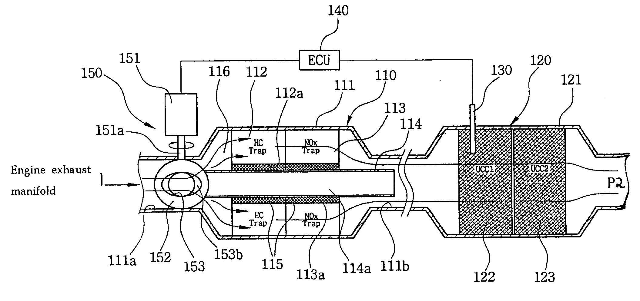
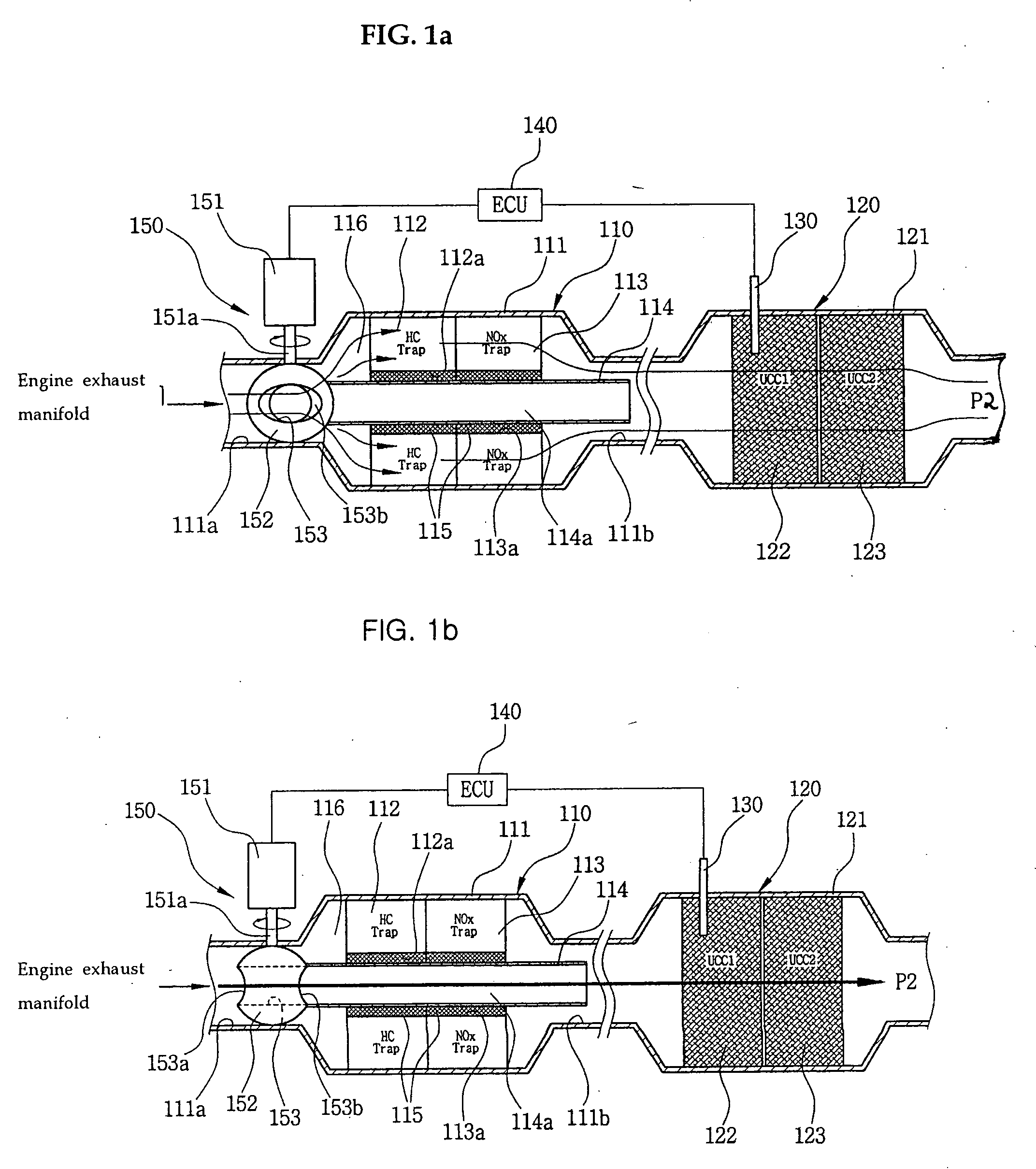
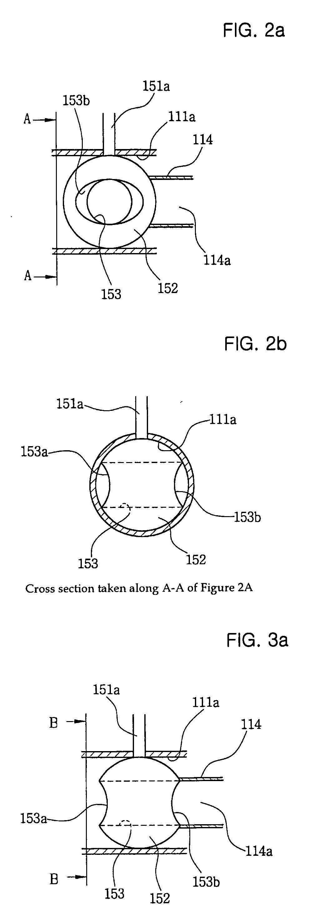
[0022]FIGS. 1a and 1b are cross-sectional views illustrating structure for an exhaust gas purification system and an operation state of the same according to the present invention, and FIGS. 2a, 2b, 3a, and 3b are cross-sectional views illustrating a flow path of an opening and closing state of a CCC entrance path based on a rotation position of a ball valve according to the present invention.

[0023]FIGS. 4a and 4b are perspective views illustrating an opening and closing state of an intermediate pipe flow path based on a rotation position of a ball valve according to the present invention.

[0024] As shown therein, a CCC 110 and a UCC 120 are installed in series along an exhaust path extended through a rear end of an automobile body wherein exhaust gases from an engine's exhaust manifold flow through the above path before they are discharged into the air. The CCC ...


PUM

PropertyMeasurementUnit
Flow rateaaaaaaaaaa

Abstract

The present invention relates to a system for purifying automobile exhaust gas capable of allowing an absorption catalyst to purify exhaust gases, where the exhaust gases flow through the absorption catalyst in a CCC at the inital start time of the engine and capable of allowing a UCC catalyst to purify exhaust gases normally by flowing the exhaust gases only through the UCC catalyst by disconnecting a flow path connected with the absorption catalyst in the CCC during a warm-up state of the UCC catalyst. The CCC is installed near an engine exhaust manifold, and a UCC is installed in a lower side of the automobile body floor. A HC absorption catalyst and a NOx absorption catalyst each having little or no precious metal carrying amount, are installed in the CCC. A variable flow path system, including a bypass flow path and a flow path switching part, is provided.

Description

CROSS-REFERENCE TO RELATED APPLICATIONS [0001] This application claims priority from Korean Application No. 10-2004-0023423, filed on Apr. 6, 2004, which is incorporated fully herein by reference. FIELD OF THE INVENTION [0002] The present invention relates to a system for purifying automobile exhaust and, in particular, to a system for purifying automobile exhaust gas of with a variable flow path system that includes a bypass flow path and a flow path switching means, wherein a Close Catalyst Converter (CCC) is installed near an engine exhaust manifold and a Underfloor Catalyst Converter (UCC) is installed in a lower side of an automobile body floor. A hydrocarbon (HC) absorption catalyst, and a NOx absorption catalyst each having little or no precious metal, are provided in the CCC. BACKGROUND OF THE INVENTION [0003] Generally, automobile exhaust gas is a gas generated by combustion of a fuel mixture and discharged into the air through an exhaust pipe. The exhaust gas has a lot of ...

Claims


Application Information

Patent Timeline
IPC IPC(8): B01D53/34F01N3/28F01N13/08B01D53/94F01N9/00F01N13/00B01D53/86F01N3/20F01N3/24F01N99/00F01N3/08
CPCB01D53/9454Y02A50/2344B01D2255/2022B01D2255/50B01D2255/91B01D2255/912F01N3/0814F01N3/0835F01N3/0842F01N3/0878F01N3/2006F01N3/2053F01N13/14F01N2410/02F01N2570/12F01N2570/14Y02T10/26Y02T10/22F01N13/0097F01N13/009F01N13/011Y02A50/2324B01D53/9495Y02T10/12Y02A50/20F01N9/00
Inventor CHOI, SUNG-MU
Owner HYUNDAI MOTOR CO LTD
Why Eureka
Try Eureka