
Anomaly monitoring system for molding machine

a monitoring system and mold machine technology, applied in the direction of electric testing/monitoring, manufacturing tools, instruments, etc., can solve the problems of failure to meet production plans, difficulty in employing shift workers, and inability to resume operation, etc., to achieve low cost fabrication, simple hardware configuration, and compact size

Inactive Publication Date: 2005-10-06
NISSEI PLASTIC IND CO LTD
View PDF13 Cites 5 Cited by
  • Summary
  • Abstract
  • Description
  • Claims
  • Application Information

AI Technical Summary

Benefits of technology

[0010] An object of the present invention is to provide an anomaly monitoring system for a molding machine, which system enables a supervisor to acquire information which specifies a molding machine having stopped because of anomaly, which is minimum necessary information that the supervisor wishes to acquire, at a remote location and by means of a communication terminal such as a cellular phone, and which system realizes such information provision by use of a considerably simple hardware configuration and therefore can be fabricated at low cost and in a compact size.
[0011] Another object of the present invention is to provide an anomaly monitoring system for a molding machine, which system eliminates necessity of mutually connecting the communication section of a monitoring apparatus (monitoring system) and the communication section of each molding machine, and eliminates necessity of performing monitoring through computer processing or active processing, to thereby simplify the control method, and enable easy and low-cost implementation from the viewpoint of software.

Problems solved by technology

Therefore, in the case where a night operation or a 24-hour continuous operation is performed without a supervisor, when the injection molding machine anomalously stops, a step necessary for resumption of operation cannot be taken, with resultant fatal problems such as failure to fulfill the production plan.
Meanwhile, in the case where a supervisor always monitors the injection molding machine, the supervisor must work at nights or on holidays, which poses a big problem for, in particular, a small-scale automated molding plant which has difficulty in employing shift workers.
However, the conventional monitoring system and apparatus for monitoring anomaly of molding machines have the following problems to be solved.
First, since a computer system or a monitoring apparatus equivalent thereto is interposed between a molding machine and mail transmission means (communication means), there is a merit such that various types of processing can be performed by use of the computer; however, the hardware configuration of the entire system becomes too complex in an effort to satisfy a user's need of knowing minimum necessary information at a remote location, whereby cost and size increase to an unignorable degree.
Second, since the communication section of a monitoring apparatus (monitoring system) and the communication section of each molding machine are mutually connected via a communication line and monitoring is performed, by means of computer processing or active processing, by a method in which the operation state of each injection molding machine is obtained at anomaly detection intervals of, for example, 5 minutes, the control method becomes complex, and cost increases to an unignorable degree because of software cost.
Third, since the molding machine must have necessary functional sections such as a communication section, the monitoring apparatus (monitoring system) cannot be attached directly to an old-type injection molding machine or the like which does not have a communication section.
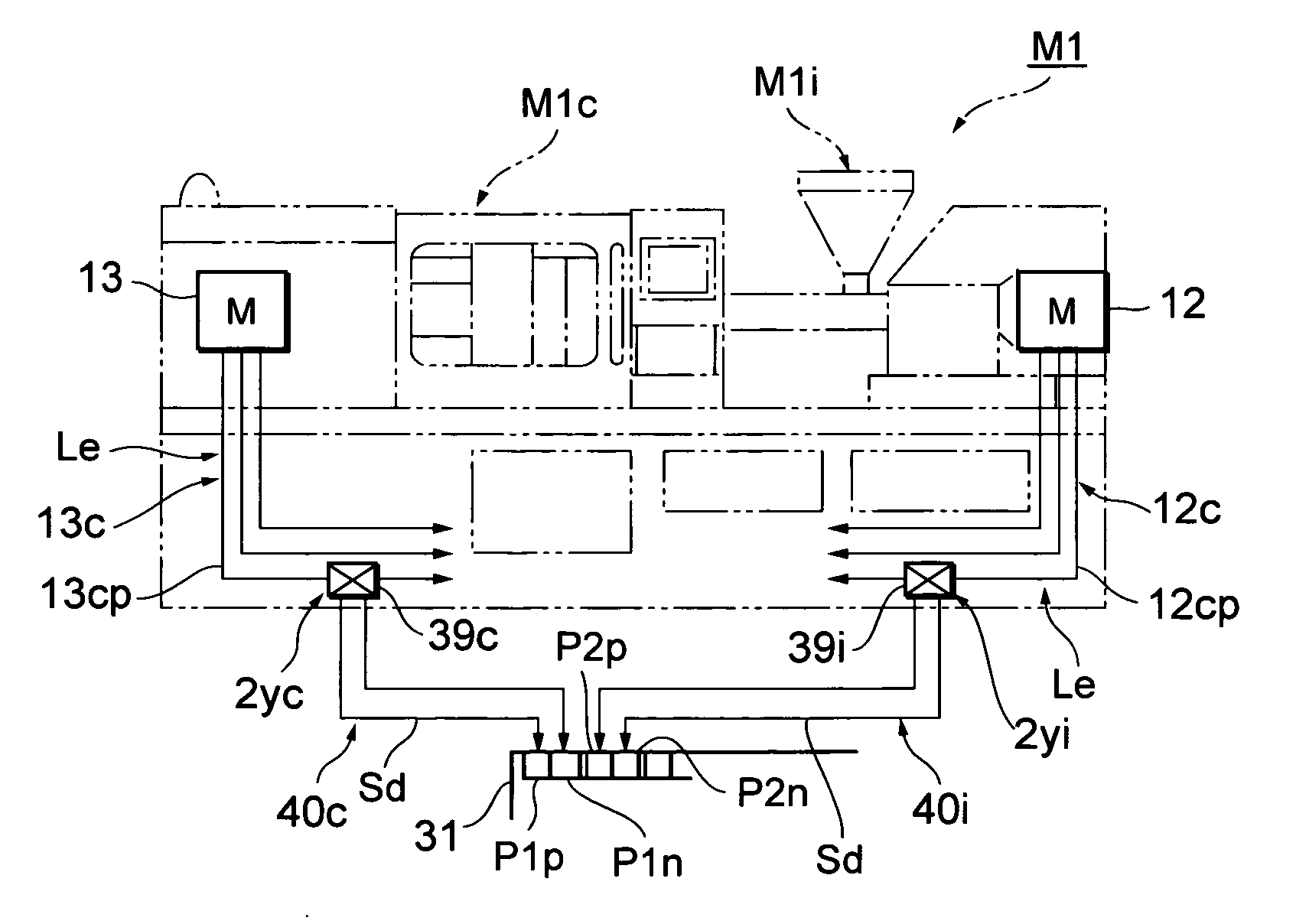
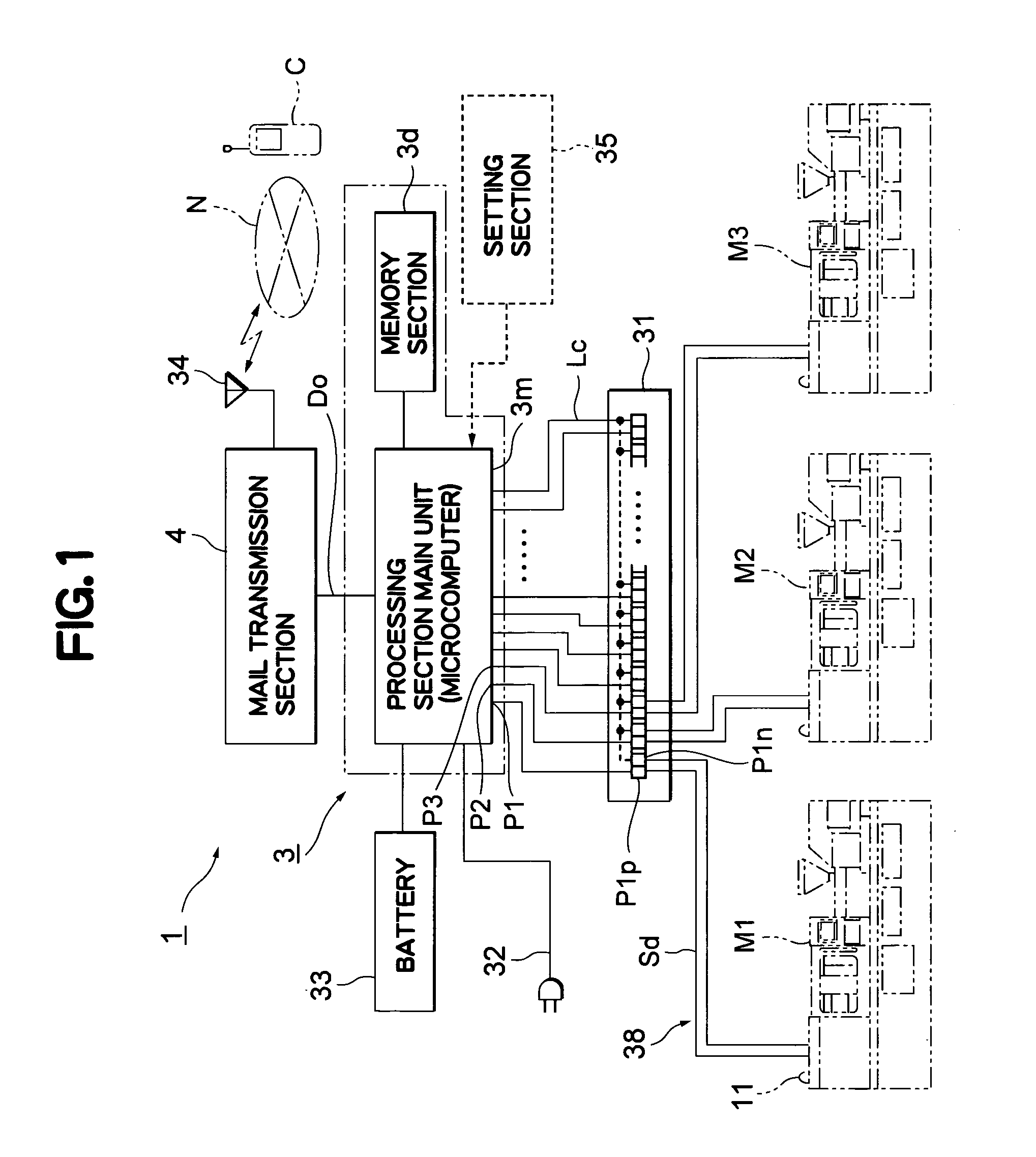
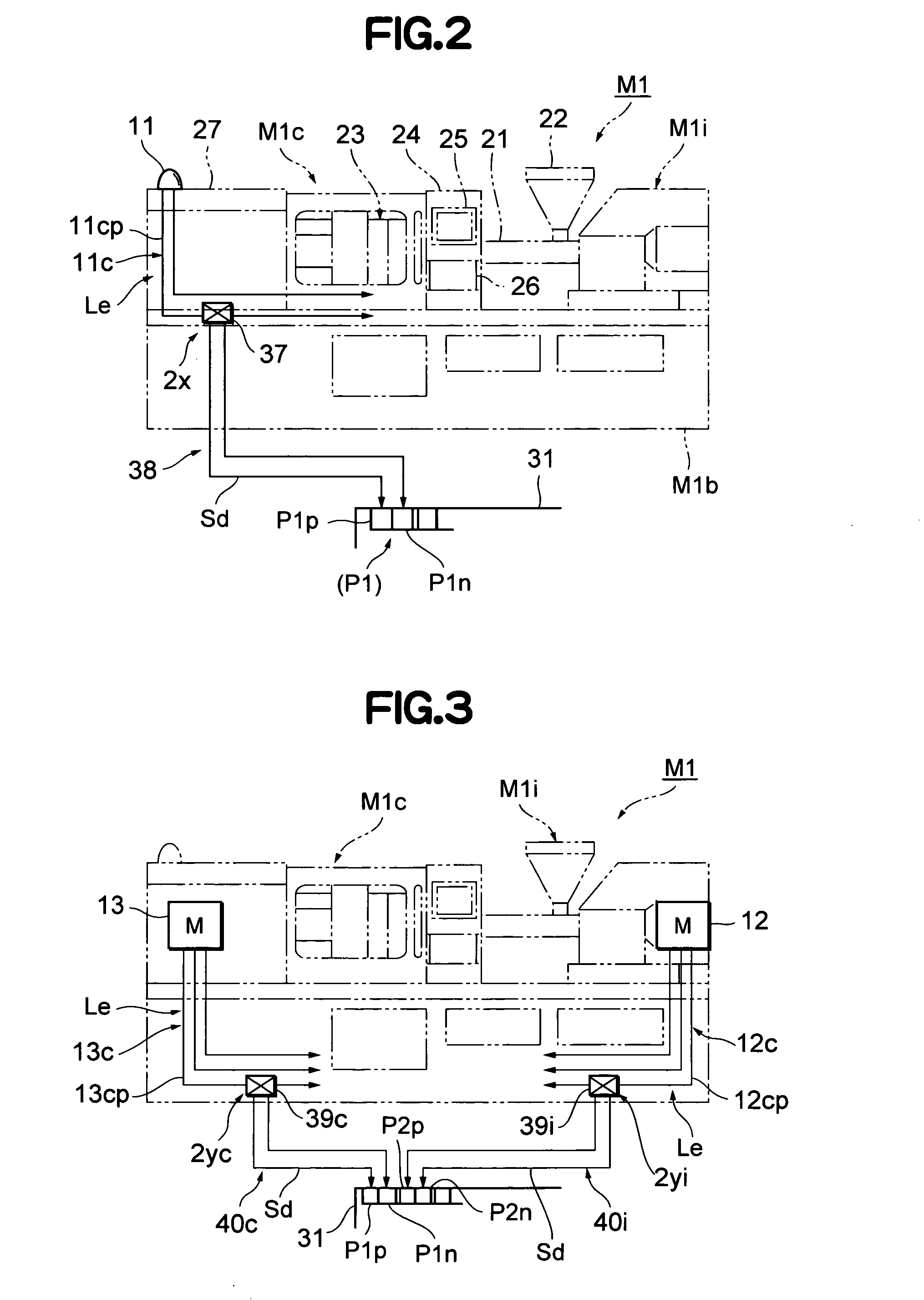
Therefore, the conventional monitoring apparatus (monitoring system) encounters difficulties in relation to attachment and general application to various molding machines.

Method used


Image

  • Anomaly monitoring system for molding machine
  • Anomaly monitoring system for molding machine
  • Anomaly monitoring system for molding machine

Examples


Embodiment Construction

[0020] An embodiment of the present invention will next be described in detail with reference to the drawings. The accompanying drawings are illustrative of the embodiment and are not meant to limit the scope of the invention. In order to describe the invention clearly, detailed description of known features is omitted.

[0021] First, the configuration of an anomaly monitoring system 1 for a molding machine according to the present embodiment will be described with reference to FIGS. 1 and 2.

[0022] In these drawings, M1, M2, and M3 represent injection molding machines to be monitored by the anomaly monitoring system 1 according to the present embodiment. As shown by an imaginary line in FIG. 2, the injection molding machine M1 includes a machine base M1b; and an injection unit M1i and a mold clamping unit M1c, which are disposed on the machine base M1b. The remaining injection molding machines M2, etc. are of the same configuration. The injection unit M1i includes a heating barrel 2...


PUM

PropertyMeasurementUnit
Timeaaaaaaaaaa
Electrical conductoraaaaaaaaaa

Abstract

Each of molding machines has a conductive line whose electrification state changes as a result of anomalous stoppage. An anomaly monitoring system includes detection sections provided in the conductive lines so as to detect the electrification states thereof; a data processing section having input ports to which the detection sections are connected, wherein, when a detection signal indicating the electrification state of a conductive line is provided from a detection section to an input port, the data processing section outputs data regarding a mail address and a message prepared in accordance with the input port having received the detection signal and the electrification state; and a mail transmission section which receives the data output from the data processing section and sends an electronic mail containing the message to a communication terminal corresponding to the mail address.

Description

BACKGROUND OF THE INVENTION [0001] 1. Field of the Invention [0002] The present invention relates to an anomaly monitoring system for a molding machine which detects an anomalous stoppage of the molding machine during continuous operation, and transmits a detection report to a communication terminal at a different location via communication means. [0003] 2. Description of the Relevant Art [0004] Generally, in an automated molding plant in which an injection molding machine is operated continuously, monitoring anomalous stop of the injection molding machine is an important task for securing productivity to thereby fulfill a production plan. Therefore, in the case where a night operation or a 24-hour continuous operation is performed without a supervisor, when the injection molding machine anomalously stops, a step necessary for resumption of operation cannot be taken, with resultant fatal problems such as failure to fulfill the production plan. Meanwhile, in the case where a supervis...

Claims


Application Information

Patent Timeline
IPC IPC(8): B22D46/00B22D17/32B29C45/76B29C45/84B29C48/92G05B23/02G06F13/00
CPCB29C45/84
Inventor WAKABAYASHI, EIKISUZUKI, KAZUNAGA
Owner NISSEI PLASTIC IND CO LTD
Learn More