Prismatic-type rechargeable battery with attached lead plate

Inactive Publication Date: 2005-10-06
SAMSUNG SDI CO LTD
View PDF2 Cites 32 Cited by
  • Summary
  • Abstract
  • Description
  • Claims
  • Application Information

AI Technical Summary

Benefits of technology

[0019] The present invention also provides a prismatic-type rechargeable battery that includes a lead plate where a protrusion on the surface of a cap plate is accomodated to prevent any floating or large gaps between the lead plate and the cap plate.

Problems solved by technology

Generally, it is difficult to connect the electrodes of a bare cell to the electric terminals of a PCM by direct welding because of the shape and composition of the bare cell.
More complications may occur when trying to weld a lead plate made of nickel to a can made of aluminum.
Because of the non-melting properties of nickel and aluminum and the excellent conductivity of aluminum, it is very difficult to use ultra-sonic welding or resistance welding.
If the laser is irradiated while the lead plate is connected to a protective circuit, electrification may occur along with an electric shock, potentially deteriorating the reliability of the safety apparatuses.
In addition, when the lead plate is directly laser welded to the bottom surface of the can, the electrolyte may leak out of the welded portion if the welding strength is not precisely controlled.
This configuration interferes with the welding process and, even when the welding can be performed, it weakens the bond that is formed.
If the welded bond between the lead plate and the cap plate is insufficiently strong, the lead plate cannot accomplish the above functions.
As a result, the mechanical strength or the electric connection of a finished rechargeable battery deteriorates.

Method used


Image

  • Prismatic-type rechargeable battery with attached lead plate
  • Prismatic-type rechargeable battery with attached lead plate
  • Prismatic-type rechargeable battery with attached lead plate

Examples


Embodiment Construction

[0029] Hereinafter, a preferred embodiment of the present invention will be described with reference to the accompanying drawings. In the following description and drawings, the same reference numerals are used to designate the same or similar components.

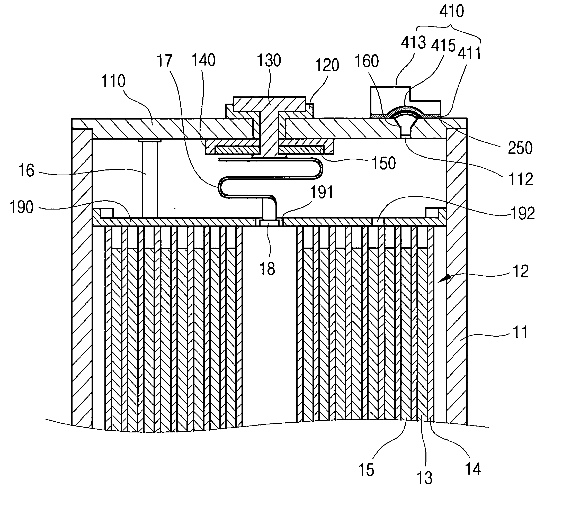
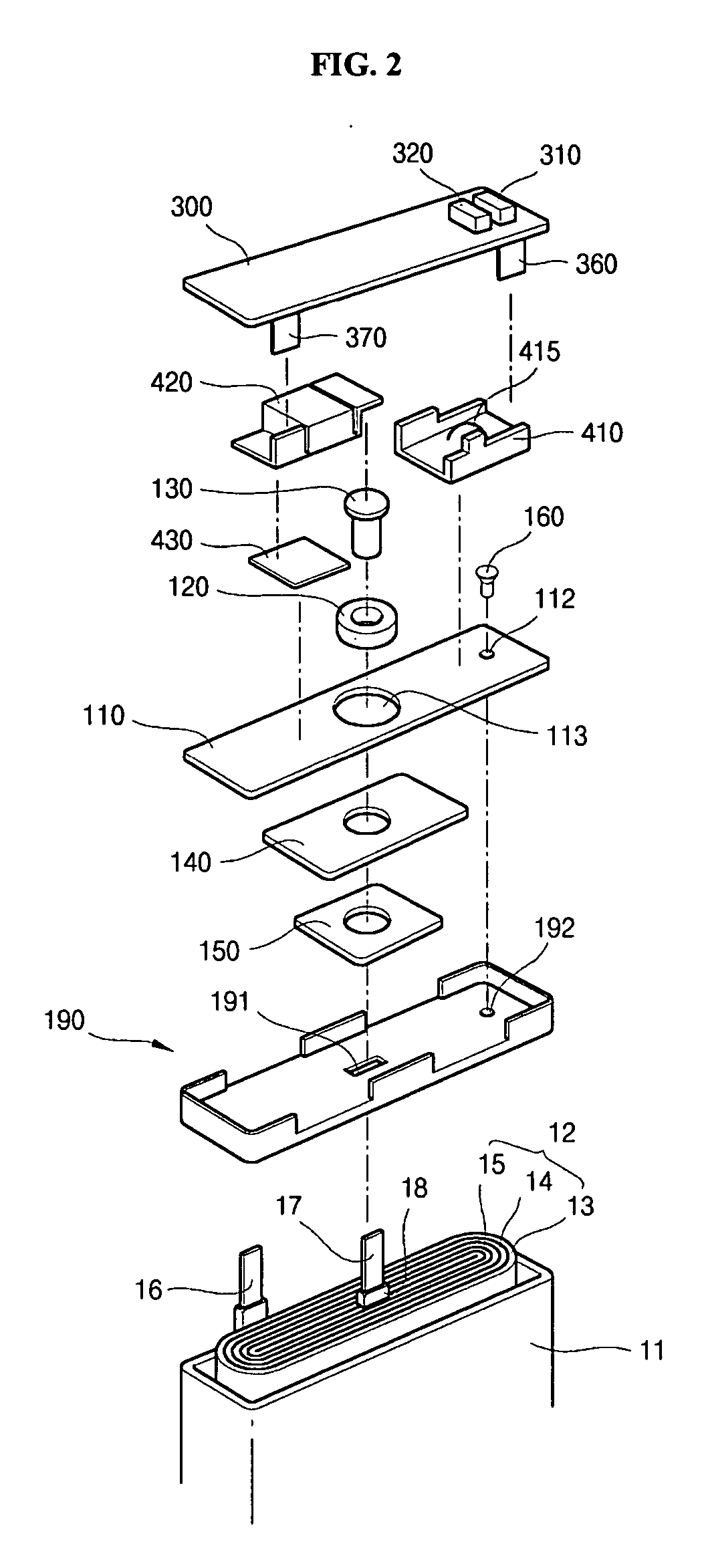
[0030]FIG. 2 depicts a lithium pack battery that has a bare cell which includes a can 11, a electrode assembly 12 contained in the can 11, and a cap assembly coupled to the open upper end of the can 11 for sealing it.

[0031] The electrode assembly 12 is formed by winding a positive electrode 13, a separator 14, and a negative electrode 15 from a thin plate or a film shape into an eddy shape. Insulating tapes 18 are wound about respective boundary portions wherein positive and negative leads 16 and 17 are led out of the electrode assembly 12, in order to prevent a short circuit between the two electrodes 13 and 15. The prismatic type can 11 is generally made of aluminum or aluminum alloy and is in the shape of a cuboid. The can 11 c...


PUM


Abstract

The present invention discloses a prismatic-type rechargeable battery that comprises a bare cell that includes an electrode assembly comprising a positive electrode, a negative electrode, and a separator, a prismatic-type can that contains the electrode assembly and an electrolyte, a cap assembly that has a cap plate for covering the open upper end of the prismatic type can, and a lead plate coupled to a part of the cap plate. An electrolyte injection hole is positioned on a side of the cap plate and the lead plate has a bottom portion for covering the electrolyte injection hole. At least a part of the bottom portion is coupled to a surface of the cap plate and the bottom portion has a convex portion which corresponds to the electrolyte injection hole.

Description

CROSS REFERENCE TO RELATED APPLICATION [0001] This application claims priority to and the benefit of Korean Patent Application No. 2004-21426 filed on Mar. 30, 2004, which is hereby incorporated by reference for all purposes as if fully set forth herein. BACKGROUND OF THE INVENTION [0002] 1. Field of the Invention [0003] The present invention relates to a rechargeable battery, and more particularly to a prismatic-type rechargeable battery that is attached to a lead plate. [0004] 2. Description of the Prior Art [0005] Recently, rechargeable batteries have been developed and used extensively, in part because they can be manufactured in compact sizes with the capacity for storing large amounts of energy. Typical examples of the rechargeable batteries include nickel-hydrogen (Ni-MH) batteries, lithium (Li) batteries, and lithium ion batteries. [0006] The bare cell of a rechargeable battery is formed by first placing an electrode assembly, which is composed of positive and negative elect...

Claims


Application Information

Patent Timeline
IPC IPC(8): H01M10/04H01M10/00H01M2/20H01M2/02H01M2/08H01M2/30H01M2/06H01M2/36H01M2/34H01M2/26H01M2/04H01M10/38H01M50/533H01M50/645
CPCH01M2/0217H01M2/26H01M2/361H01M2/365H01M10/0436Y02E60/10H01M50/103Y02P70/50H01M50/645H01M50/533
Inventor KIM, IN HAN
Owner SAMSUNG SDI CO LTD
Why Eureka
Try Eureka