Radio frequency device and mobile communication terminal using the same

a mobile communication terminal and radio frequency circuit technology, applied in the direction of amplifiers wit coupling networks, substation equipment, electrical apparatus, etc., can solve the problems of increasing the loss downstream of the transistor output terminal, difficult to realize the low-pass type circuit, and the inability to use a circuit block to be disposed between the radio frequency power amplifier and the antenna in the case of modulation technique, etc., to achieve the effect of reducing costs, reducing terminal size and reducing terminal siz

Inactive Publication Date: 2005-10-06
RENESAS ELECTRONICS CORP
View PDF15 Cites 41 Cited by
  • Summary
  • Abstract
  • Description
  • Claims
  • Application Information

AI Technical Summary

Benefits of technology

[0007] The key to popularize the mobile communication terminal is to downsize the terminal and reduce the costs. In addition, it is important that the mobile communication terminal responds to a plurality of signals that are different in the frequency band and the modulation technique. For this reason, there are a multi-band system that is responsive to a plurality of frequency bands and a multi-mode system tha...

Problems solved by technology

However, because the switch is disposed between the transistor output terminal that is low in the impedance and the matching network, a circuit loss downstream of the transistor output terminal increases due to a parasitic resistance of the switch, and the performance of the radio frequency power amplifier is not prevented from being deteriorated.
However, because one of the output matching networks is made up of a low-pass type circuit, and the other output matching network is made up of a high-pass type circuit, in the case where the frequency bands of two signals are in proximity to each other, it is difficult to realize th...

Method used


Image

  • Radio frequency device and mobile communication terminal using the same
  • Radio frequency device and mobile communication terminal using the same
  • Radio frequency device and mobile communication terminal using the same

Examples


first embodiment

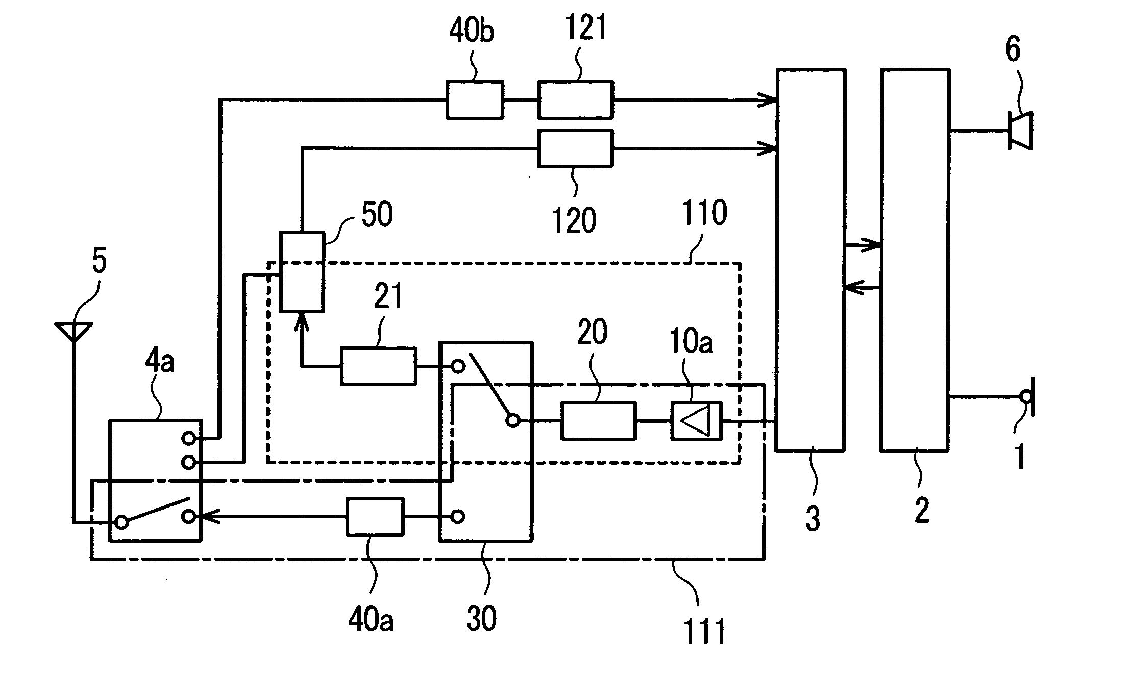
[0032]FIG. 1 shows a first embodiment of the present invention. Referring to FIG. 1, reference numeral 1 denotes a microphone, 2 is a baseband signal processor, and 3 is a frequency converter circuit device (hereinafter referred to as “RF-IC”) that converts a baseband signal into a radio frequency signal, or converts the radio frequency signal into the baseband signal. Also, reference 10a denotes a radio frequency power amplifier, 20 and 21 are matching networks, 30 is a switch, 40a is a filter, 50 is a duplexer, 4a is an antenna switch, and 5 is an antenna. Reference numeral 110 surrounded by a dotted line in FIG. 1 and reference numeral 111 surrounded by a dashed line in FIG. 1 denote the first transmitter path including the duplexer 50 and the second transmitter path including no duplexer 50, respectively. In addition, reference 40b denotes a filter, 120 and 121 are radio frequency receiver circuit devices, and 6 is a speaker. The mobile communication terminal is constituted by a...

second embodiment

[0065]FIG. 6 shows a second embodiment of the present invention. Referring to FIG. 6, reference numeral 22 denotes a matching network, 31 is a switch, and 500a is a watershed that connects the transmitter path 110 and 111.

[0066] The circuit operation of this embodiment will be described with reference to FIG. 6. The operation of a circuit that is made up of a microphone 1, a baseband signal processor 2 and an RF-IC 3 and converts a sound signal into a radio frequency transmitter signal in frequency, the structure and operation of a receiver circuit that is made up of the filter 40b, the radio frequency receiver circuit devices 120 and 121, the RF-IC 3, the baseband signal processor 2 and the speaker 6, and the operation of the antenna switch 4a are identical with those in the first embodiment (FIG. 1).

[0067] The radio frequency transmitter signal TxA for the W-CDMA system, which has been outputted from the RF-IC 3, is amplified up to a desired power in the radio frequency power am...

third embodiment

[0076]FIG. 8 is a third embodiment of the present invention. Referring to FIG. 8, reference 500b denotes a watershed that connects the transmitter paths 110 and 111.

[0077] The circuit operation of this embodiment will be described with reference to FIG. 8. The operation of a circuit that is made up of a microphone 1, a baseband signal processor 2 and an RF-IC 3 and converts a sound signal into a radio frequency transmitter signal in frequency, the structure and operation of a receiver circuit that is made up of the filter 40b, the radio frequency receiver circuit devices 120 and 121, the RF-IC 3, the baseband signal processor 2 and the speaker 6, and the operation of the antenna switch 4a are identical with those in the first embodiment (FIG. 1).

[0078] The radio frequency transmitter signal TxA for the W-CDMA system, which has been outputted from the RF-IC 3, is amplified up to a desired power in the radio frequency power amplifier 10a, and transmitted to the duplexer 50 through t...


PUM


Abstract

There is provided a radio frequency circuit device for multi-band and multi-mode which is low in a circuit loss, and a mobile communication terminal using the radio frequency circuit device. The radio frequency circuit device has a first path 110 that includes an amplifier 10a that amplifies signals of at least two modulation techniques in power, a matching network 20 that is connected to the amplifier and a duplexer 50 and allows the matching network to be coupled with an antenna, and a second path 111 that does not include the duplexer and allows the matching network to be coupled with the antenna. The first path is selected when the amplifier amplifies one of the signals of at least two modulation techniques, and the second path is selected when the amplifier amplifies another signal. An output impedance of the amplifier is matched with an impedance when viewing the antenna side from the amplifier in the first path and the second path.

Description

CLAIM OF PRIORITY [0001] The present application claims priority from Japanese application JP 2004-102484 filed on Mar. 31, 2004, the content of which is hereby incorporated by reference into this application. FIELD OF THE INVENTION [0002] The present invention relates to a radio frequency circuit device suitable for a mobile communication terminal, and more particularly to a radio frequency circuit device that deals with a plurality of signals that are different in a frequency band or a modulation technique from each other and a mobile communication terminal using the radio frequency circuit device. BACKGROUND OF THE INVENTION [0003] A mobile communication terminal represented by a cellular phone becomes increasingly popular around the world. A radio frequency circuit for use in the mobile communication terminal is disclosed in, for example, Japanese Patent Laid-Open No. H9-232887, Japanese Patent Laid-Open No. H10-56340and Japanese Patent Laid-Open No. H11-112251. [0004] An exampl...

Claims


Application Information

Patent Timeline
IPC IPC(8): H04B1/44H03F3/60H04B1/04H04M1/00
CPCH04B1/0458H04B1/0483
Inventor KURIYAMA, AKIRAYAMAWAKI, TAIZOTANAKA, SATOSHI
Owner RENESAS ELECTRONICS CORP
Why Eureka
Try Eureka