Method and apparatus for aligning a knee for surgery or the like

a knee and knee joint technology, applied in the field of manipulation of legs, can solve the problems of overload in the compartment, damage, incorrect placement of the prosthesis, etc., and achieve the effects of reducing the number of people required, reducing the need for bone drilling, and increasing the speed of knee replacement surgery

Inactive Publication Date: 2005-10-06
ERMI +1
View PDF11 Cites 192 Cited by
  • Summary
  • Abstract
  • Description
  • Claims
  • Application Information

AI Technical Summary

Benefits of technology

[0015] It is a further object of the present invention to provide an improved method and apparatus for aligning a knee joint of a patient.
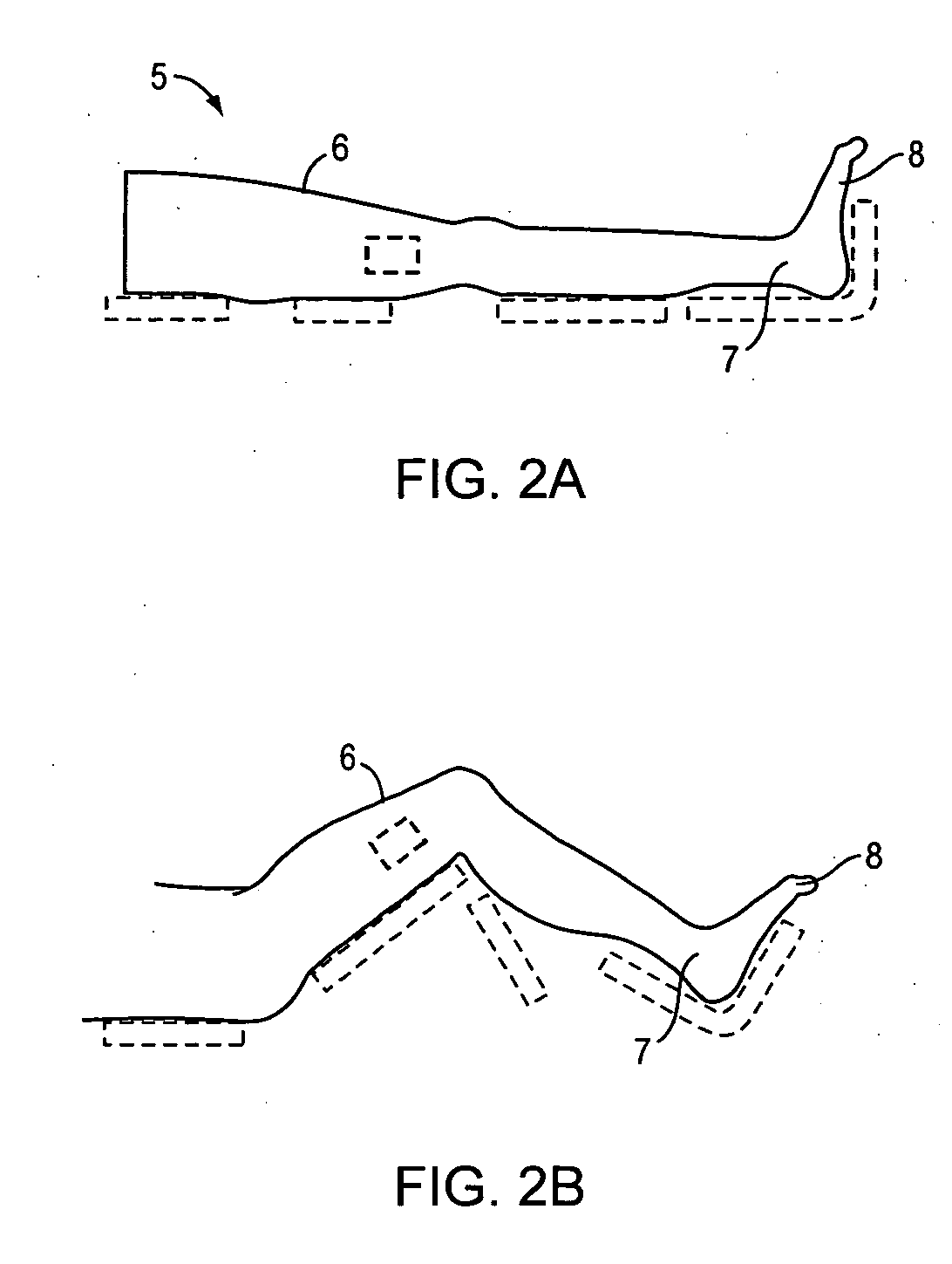
[0018] It is a further object of the present invention to provide an improved method and apparatus for aligning the knee while in a bent condition.
[0019] It is a further object of the present invention to provide a method and apparatus to increase the speed of knee replacement surgery.
[0020] It is a further object of the present invention to provide an improved method and apparatus to reduce the number of persons required to perform a UKA or TKA.
[0021] It is a further object of the present invention to provide an improved method and apparatus to reduce the need for drilling into bone to secure cutting guides during knee replacement surgery.
[0022] It is a further object of the present invention to provide an inflatable bladder under the thigh to provide distraction of the knee joint when the leg is in the bent or flexion position.

Problems solved by technology

When this load exceeds a certain level in one or the other compartment, overload in that compartment occurs and damage ensues.
The damage begins with articular cartilage wear and can progress to flattening of the condyle with its resultant shape change in the condyle.
Each of these failures can be attributed to misalignment of the implant.
This procedure has numerous disadvantages including inaccurate cutting of the bone resulting in incorrect placement of the prosthesis and blood clots that may occur from forcing the rod into the marrow of the thighbone to estimate the mechanical axis.
However, the measurements tend to be inaccurate because they are taken from the somewhat deformable tissue covering the bone rather than the more rigid bone itself.
The securing process may weaken the bone and increase the recovery time.
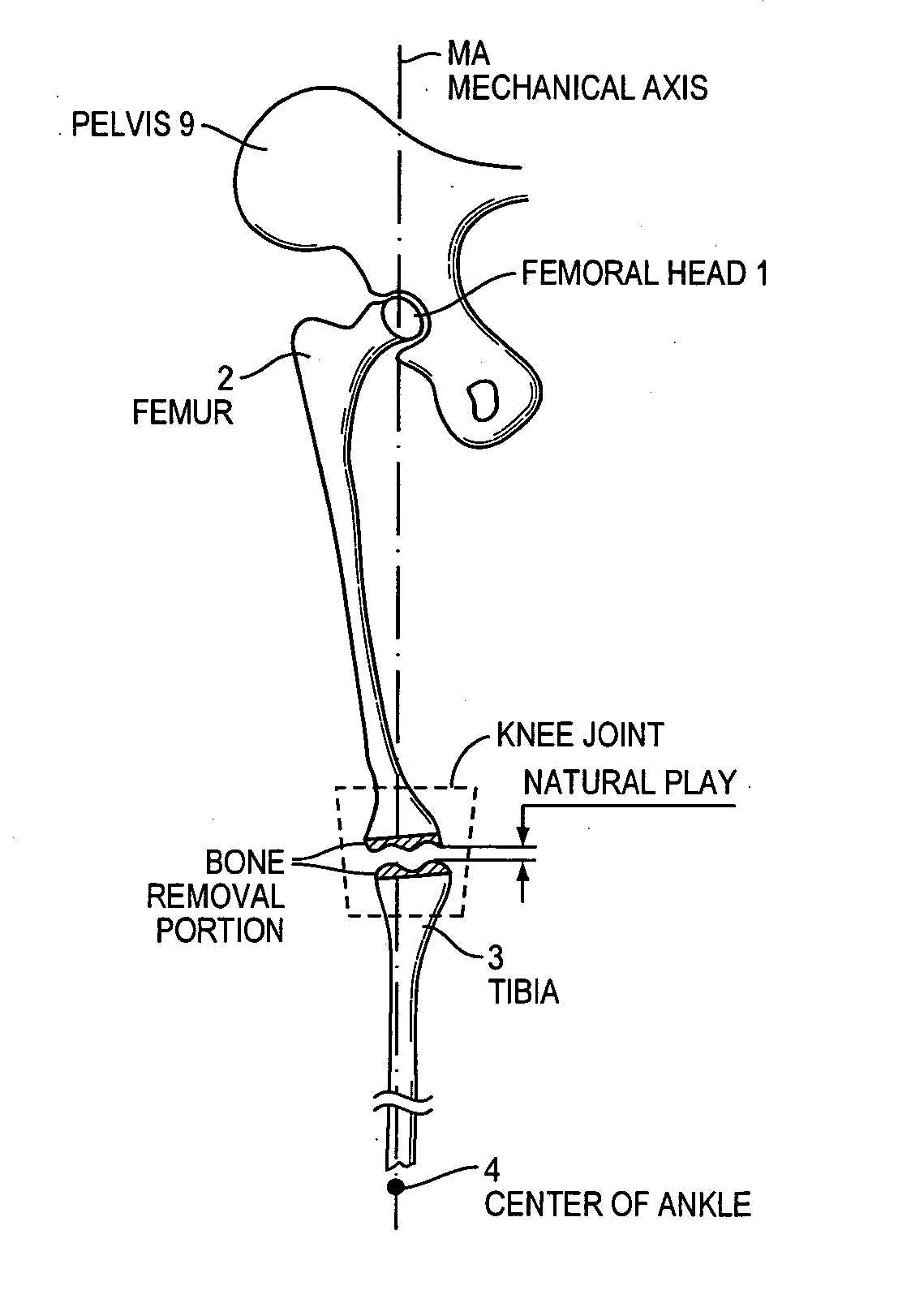
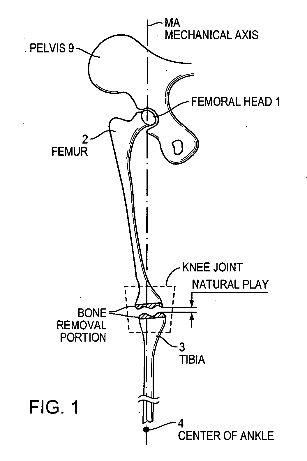
The current known methods do not provide a method of determining the natural play of a joint.

Method used


Image

  • Method and apparatus for aligning a knee for surgery or the like
  • Method and apparatus for aligning a knee for surgery or the like
  • Method and apparatus for aligning a knee for surgery or the like

Examples


Embodiment Construction

[0048] The present inventions now will be described more fully hereinafter with reference to the accompanying drawings, in which some, but not all embodiments of the invention are shown. Indeed, these inventions may be embodied in many different forms and should not be construed as limited to the embodiments set forth herein; rather, these embodiments are provided so that this disclosure will satisfy applicable legal requirements. Like numbers refer to like elements throughout.

[0049] Many modifications and other embodiments of the inventions set forth herein will come to mind to one skilled in the art to which these inventions pertain having the benefit of the teachings presented in the foregoing descriptions and the associated drawings. Therefore, it is to be understood that the inventions are not to be limited to the specific embodiments disclosed and that modifications and other embodiments are intended to be included within the scope of the appended claims. Although specific te...


PUM


Abstract

Generally described the invention relates to methods and apparatuses for aligning the lower extremities of a patient with a mechanical axis. More specifically, the present invention provides an exoskeleton or external framework that positions a patient's leg into a desired mechanical axis in preparation for surgery or other medical treatment.

Description

CROSS REFERENCE SECTION [0001] This application claims the benefit and priority of U.S. Provisional Application No. 60 / 552,641, filed Mar. 11, 2004, which is incorporated herein in its entirety.FIELD OF THE INVENTION [0002] The present invention is generally related to the manipulation of a leg to provide surgery thereon or other medical attention thereto. More specifically, the present invention provides an external frame, or “exoskeleton” to position the leg into a desired axis in preparation for surgery or other treatment on the knee. [0003] 2. Background of the Invention [0004] Damage to the weight-bearing surfaces of the knee as a result of arthritis and / or trauma can be isolated to one compartment, or can be global (involving two or more of the three compartments of the knee). The three compartments of the knee are the patellofemoral compartment, the medial compartment and the lateral compartment. When damage to the knee results in a change in the shape of the underlying bone ...

Claims


Application Information

Patent Timeline
Patent Type & Authority Applications(United States)
IPC IPC(8): A61B17/00A61B17/15A61F2/46A61G13/12
CPCA61B17/154A61B2017/00557A61B2017/565A61F2002/4658A61F2002/4666
Inventor BRANCH, THOMAS P.SATTLER,, ALEXANDER JR.WESTIN, FREDRIK
Owner ERMI
Why Eureka
Try Eureka