Retinal prosthesis with side mounted inductive coil

a technology of inductive coils and prostheses, applied in the field of visual prosthesis, can solve the problems of large prosthetic devices, inability to produce adequate simulated vision to truly aid the visually impaired, and devices cannot be powered by wires

Active Publication Date: 2005-10-06
SECOND SIGHT MEDICAL PRODS +2
View PDF17 Cites 97 Cited by
  • Summary
  • Abstract
  • Description
  • Claims
  • Application Information

AI Technical Summary

Benefits of technology

[0017] Applicants have discovered that a coil around the sclera at or near 90 degrees rotation toward the lateral side of the eye has several advantages over previous designs. The secondary coil will not irritate the conjunctiva as it is placed against the sclera under the lateral rectus muscle, well behind the region where the conjunctiva attaches to the surgical limbus which is most susceptible to irritation. There is also more room between the conjunctiva and sclera on the side of the eye compared to the front of the eye. The primary coil can be placed on the temples of a pair of glasses and / or hidden by the user's hair. The spacing between primary and secondary coil can be as close, or closer, than that allowed for a coil pair located in the front of the eye or at a 45 degree angle because there are no eyelids or eyelashes to interfere with the coil.
[0018] The skull is relatively flat and thin at the temple outside the lateral side of the eye. This allows for close coupling of the primary and secondary coils. The secondary coil can be mounted on the sclera under the lateral rectus muscle allowing the coil to move with the eye, avoiding the need for a cable that flexes with eye movement.
[0021] Further, an implanted electronics package is required to process and send the visual signal to the electrodes. It is advantageous to place the electronics package outside the sclera to aid heat dissipation. The electronics package can be attached to the strap or directly to the coil. This would not be possible with a front coil configuration as there is not enough room under the conjunctiva to accommodate the electronics package and coil near the limbus.

Problems solved by technology

While some of these early attempts met with some limited success, these early prosthetic devices were large, bulky and could not produce adequate simulated vision to truly aid the visually impaired.
The device can not be powered by wires as any connection through the skin will create the risk of infection.
Battery power is not practical as batteries are bulky and surgery is required to replace them.
Implanting within the lens capsule is difficult surgery and only allows for a small diameter coil.
Implanting around the sclera under the conjunctiva and near the surgical limbus (that is at the front of the eye) allows for a larger coil but may cause irritation or damage to the conjunctiva if the coil is placed in front near the cornea.

Method used


Image

  • Retinal prosthesis with side mounted inductive coil
  • Retinal prosthesis with side mounted inductive coil
  • Retinal prosthesis with side mounted inductive coil

Examples


Embodiment Construction

[0029] The following description is of the best mode presently contemplated for carrying out the invention. This description is not to be taken in a limiting sense, but is made merely for the purpose of describing the general principles of the invention. The scope of the invention should be determined with reference to the claims.

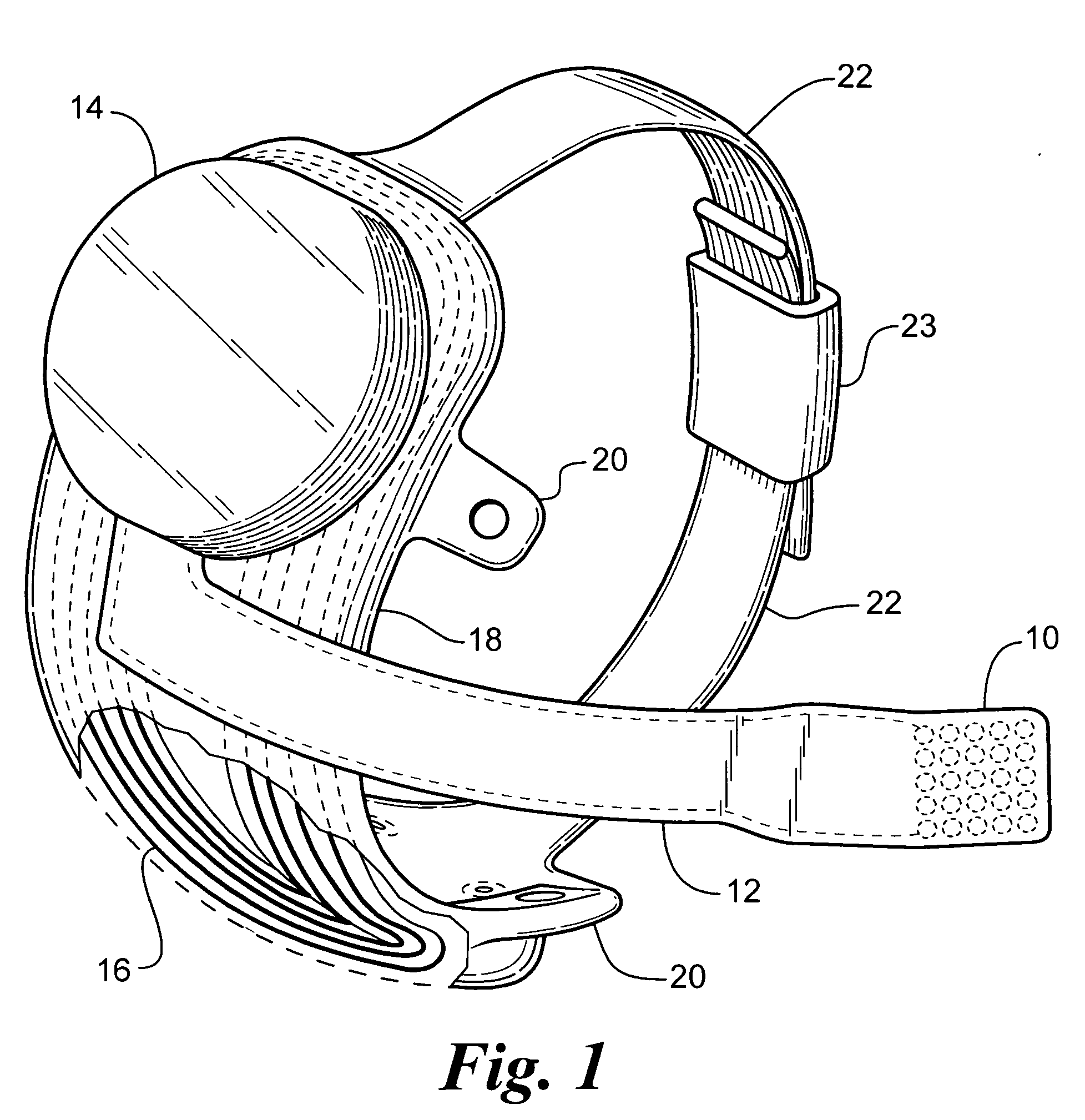
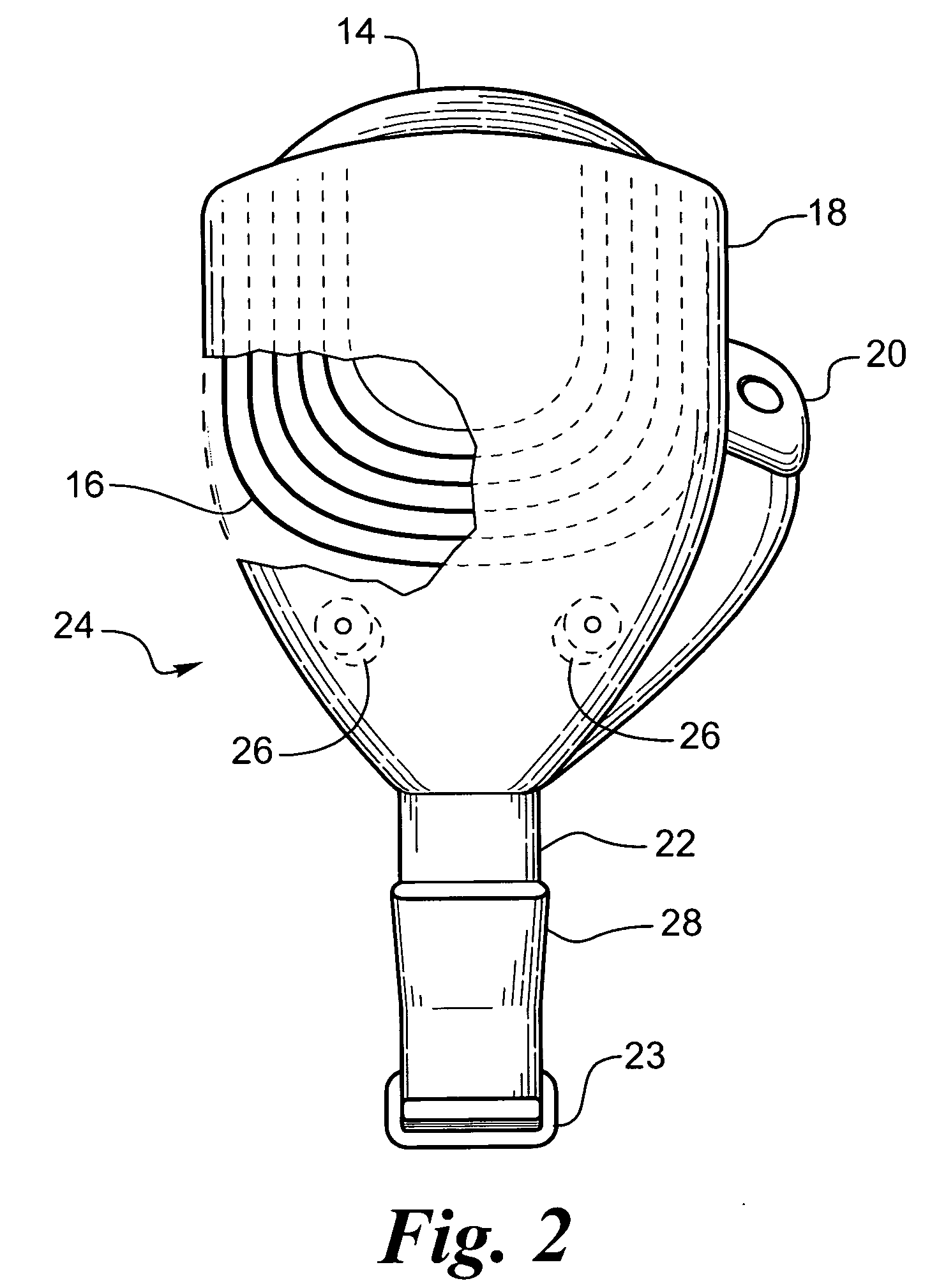
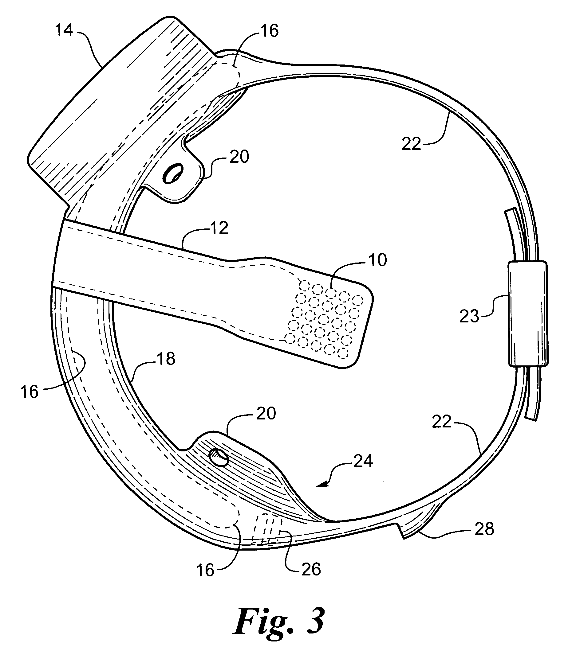
[0030]FIG. 1 shows a perspective view of the implanted portion of the preferred retinal prosthesis. An electrode array 10 is mounted by a retinal tack or similar means to the epiretinal surface. The electrode array 10 is electrically coupled by a cable 12 which pierces the sclera and is electrically coupled to an electronics package 14, external to the sclera.

[0031] The electronics package 14 is electrically coupled to a secondary inductive coil 16. Preferably the secondary inductive coil 16 is made from wound wire. Alternatively, the secondary inductive coil may be made from a thin film polymer sandwich with wire traces deposited between layers of thin f...


PUM


Abstract

The invention is a retinal prosthesis with an inductive coil mounted to the side of the eye by means of a strap around the eye. This allows for close coupling to an external coil and movement of the entire implanted portion with movement of the eye ball.

Description

GOVERNMENT RIGHTS NOTICE [0001] This invention was made with government support under grant No. R24EY12893-01, awarded by the National Institutes of Health. The government has certain rights in the invention.FIELD OF THE INVENTION [0002] The present invention is generally directed to a visual prosthesis and more specifically to an improved mechanical and electrical configuration for retinal prosthesis for artificial vision. BACKGROUND OF THE INVENTION [0003] In 1755 LeRoy passed the discharge of a Leyden jar through the orbit of a man who was blind from cataract and the patient saw “flames passing rapidly downwards.” Ever since, there has been a fascination with electrically elicited visual perception. The general concept of electrical stimulation of retinal cells to produce these flashes of light or phosphenes has been known for quite some time. Based on these general principles, some early attempts at devising a prosthesis for aiding the visually impaired have included attaching e...

Claims


Application Information

Patent Timeline
Patent Type & Authority Applications(United States)
IPC IPC(8): A61N1/00A61N1/05A61N1/36
CPCA61N1/0543A61N1/36046A61N1/3787
Inventor GREENBERG, ROBERTHUMAYAN, MARKLITTLE, JAMESWILKIN, KEVINCHANG, DA-YUAGRAWAL, RAJAT
Owner SECOND SIGHT MEDICAL PRODS
Why Eureka
Try Eureka