Method and system for remote browsing of computer files using a bar code reader

a bar code reader and remote browsing technology, applied in the field of bar code reader remote browsing of computer files, can solve the problems of complex structure, high cost and difficulty in modification of customized systems for specific applications, and general impracticality of multi-user electronic message systems, etc., and achieve the effect of easy adaptation to different applications

Inactive Publication Date: 2005-10-06
KLEIN JOHN +2
View PDF6 Cites 76 Cited by
  • Summary
  • Abstract
  • Description
  • Claims
  • Application Information

AI Technical Summary

Benefits of technology

[0015] There may be provided a portable computer device comprising a main body and at least one data collection/communications module connectable to the main body, the main body including an interface for connection with the module, a processor for processing information received from the mod

Problems solved by technology

The manufacture of a customized system for a specific application is expensive and difficult to modify if it is subsequently desired to incorporate further data capture options than those originally provided in the customized device.
Further li

Method used


Image

  • Method and system for remote browsing of computer files using a bar code reader
  • Method and system for remote browsing of computer files using a bar code reader
  • Method and system for remote browsing of computer files using a bar code reader

Examples


Embodiment Construction

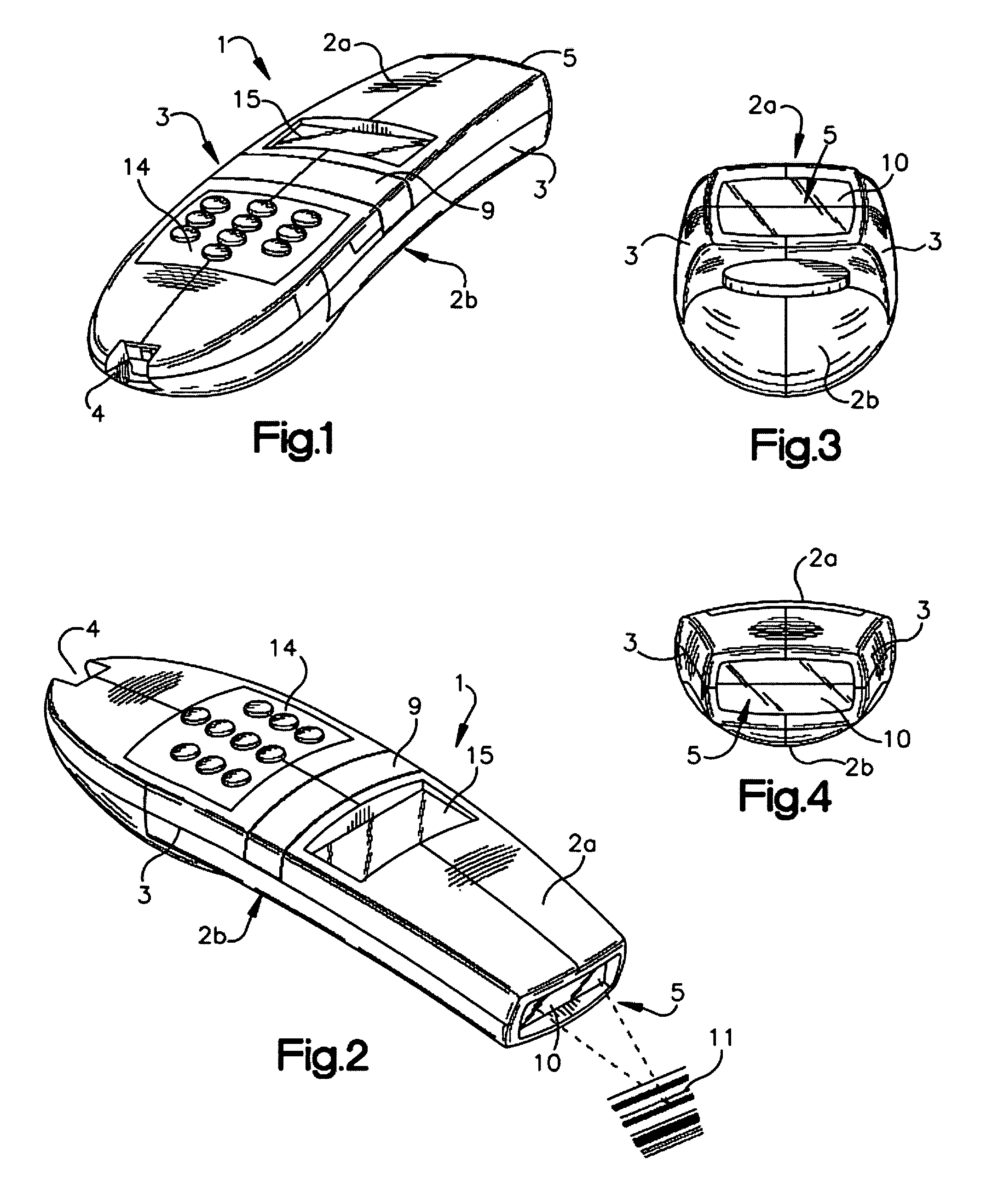
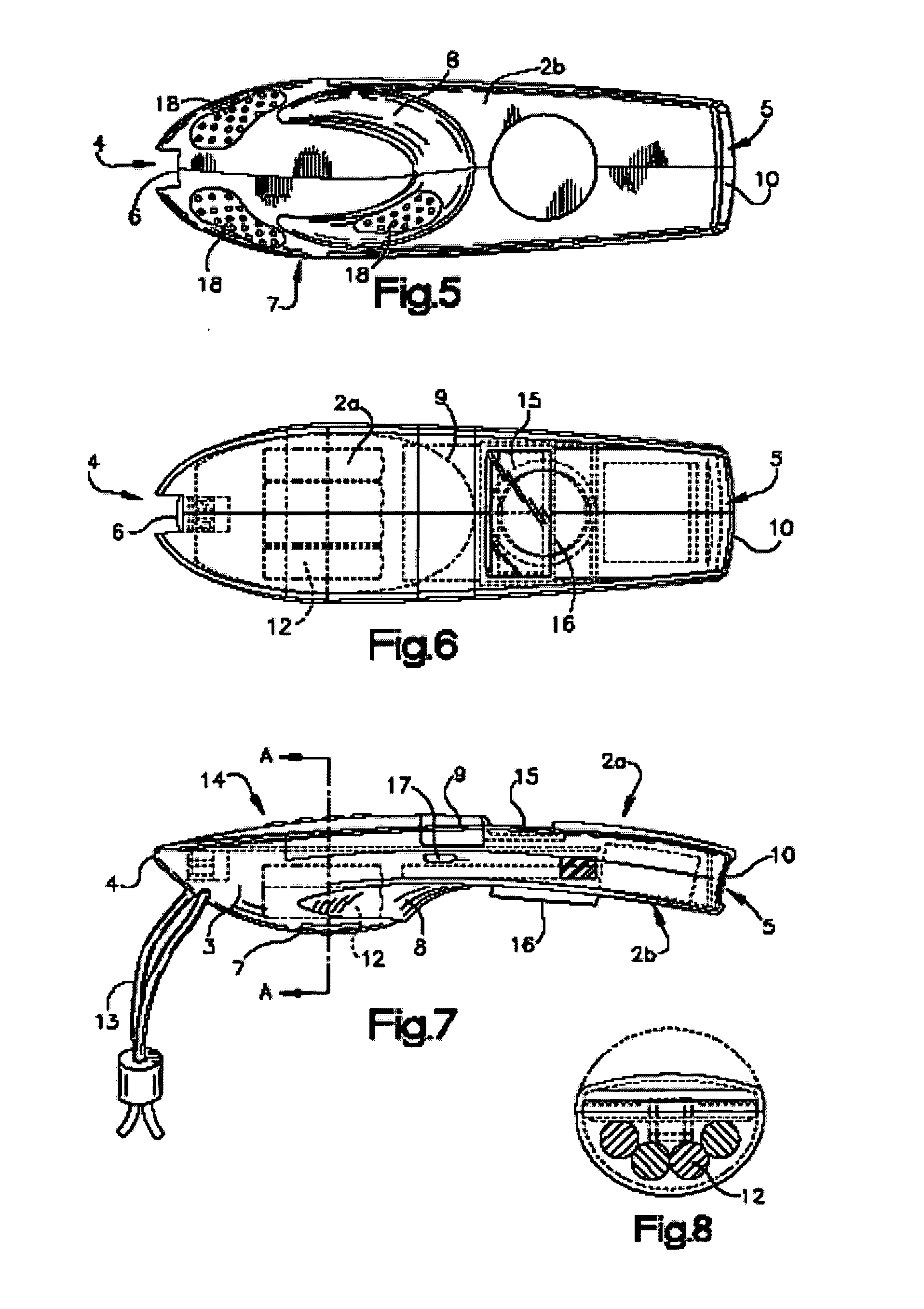
[0049] Throughout the description of the optical reader the terms “front”, “rear”, “upper”, “above”, “lower” and “below” are used consistently. Referring, for example, to FIGS. 1 to 4 the optical reader has a rear end 4 and a generally planar front end 5, an upper face 2a and opposed to that a lower face 2b.

[0050] Referring to FIGS. 1 to 4 in more detail the optical reader includes a generally bar-shaped elongate housing indicated generally by the reference numeral 1, having two generally opposed long broad upper and lower faces 2a, 2b (see also FIG. 7), two generally opposed long, shallow side faces 3, a rear end 4 and a front end 5 (see also FIG. 6).

[0051] As can be seen from FIGS. 5 and 6, the upper and lower faces 2a, 2b of the reader comprise side edges having substantially straight front portions tapering inwardly towards the front edge which is of convex shape having a large radius of curvature. The rear portions of the side edges curve inwardly and meet so that the rear en...


PUM


Abstract

A method of integrating host application software with data collection devices (e.g., bar code scanners) located on remote, wireless terminals. A data collection object executes on the host computer, using a predetermined interface between the host application software and the data collection object. That interface, and the communications between the host application software and the data collection object, are configured so that to the host application software the data collection device appears to be local hardware on the host computer. The data collection object creates and executes threads of execution for controlling operation of the data collection device, with the threads communicating with the remote terminals via a host computer transport layer, the wireless link, and a remote computer transport layer at the remote terminals. A data collection device driver on the remote terminal receives communications from the data collection object, and returns information to the data collection object, over the remote computer transport layer, wireless link, and host computer transport layer.

Description

CROSS REFERENCE TO RELATED APPLICATIONS [0001] This application is a continuation of U.S. patent application Ser. No. 08 / 916,605, filed on Aug. 22, 1997 (hereby incorporated by reference), which is a continuation of U.S. patent application Ser. No. 08 / 691,263, filed on Aug. 2, 1996, now abandoned, which was copending with U.S. Provisional Application No. 60 / 006,872, filed on Nov. 17, 1995.BACKGROUND OF THE INVENTION [0002] The invention relates to integrating host application software with data collection devices (e.g., bar code scanners) located on remote, wireless terminals. [0003] Various readers and optical scanning systems have been developed for reading printed indicia such as bar code symbols appearing on a label or the surface of an article and providing information concerning the article such as the price or nature of the article. The bar code symbol itself is a coded pattern of indicia comprised of, for example, a series of bars of various widths spaced apart from one anot...

Claims


Application Information

Patent Timeline
IPC IPC(8): G06F1/16G06F1/18G06F3/033G06F13/00G06F17/30G06K7/10G06K17/00H04L12/28H04L12/56H04L12/58H04L29/12
CPCG06F1/1616H04W76/10G06F1/1632G06F1/1656G06F1/1696G06F1/181G06F3/03545G06K7/10881G06K17/0022H04L29/12009H04L61/00H04W4/00H04W74/00H04W88/06H04L51/00G06F16/955G06F16/434G06F16/9554G06F1/1626H04L51/216H04L51/222
Inventor KLEIN, JOHNHERROD, ALLANWOLOSCHIN, STEVEN
Owner KLEIN JOHN
Why Eureka
Try Eureka