Measuring device for measuring the volume flow or the substance properties of a gas, whose direction of flow can reverse

Inactive Publication Date: 2005-10-13
DRAGERWERK AG
View PDF11 Cites 11 Cited by
  • Summary
  • Abstract
  • Description
  • Claims
  • Application Information

AI Technical Summary

Benefits of technology

[0008] The object of the present invention is to provide a device for measuring the volume flow or the substance properties of a gas, whose direction of flow can reverse, which device makes

Problems solved by technology

The uncoupling of the volume flows can never be complete for anatomic and technological reasons.
If additional flow-carrying components, for example, sensor heads with flow sensors, are inserted between the tube and the Y-piece, these also increase the dead volume of the respiration unit.
This may be due to various impairments in the functionality of the respiratory system or a small lung volume.
However, the integration of additional components implies an increased effort for installa

Method used


Image

  • Measuring device for measuring the volume flow or the substance properties of a gas, whose direction of flow can reverse
  • Measuring device for measuring the volume flow or the substance properties of a gas, whose direction of flow can reverse
  • Measuring device for measuring the volume flow or the substance properties of a gas, whose direction of flow can reverse

Examples


Example

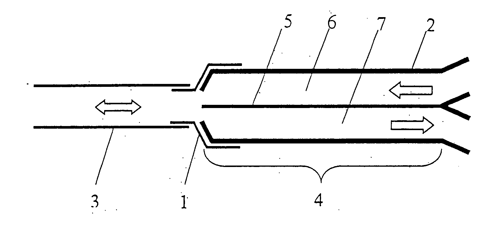
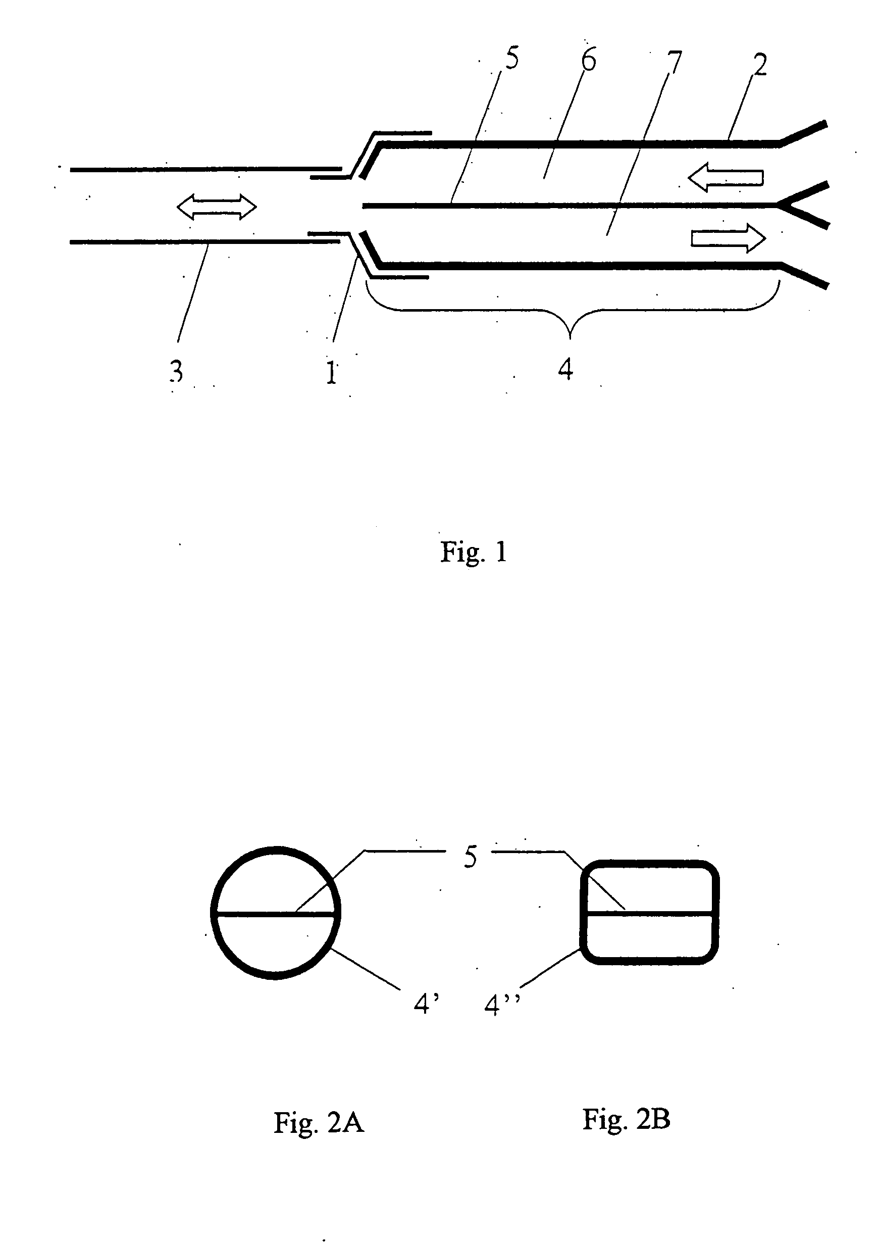
[0043] Referring to the drawings in particular, FIG. 1 shows a Y-piece 2 according to the present invention connected to a tube 3 via a tube adapter 1 in a respiration unit for mechanical respiration. The base area (or parallel section) 4 of the Y-piece is divided by a flat partition 5 into two separate flow paths 6, 7 extending in parallel to one another. During respiration, inspiration takes place via one flow path 6, and expiration via the other flow path 7. Both flow paths extend at first direction flow passage 66 and second direction flow passage 77 to the connection pieces (not shown here) of the Y-piece 2, to which additional gas-carrying components, such as breathing tubes or the like, may be connected. On the patient side, the separation of the flow paths 6, 7 ends in the area of the tube adapter 1 (ends at an opening that is a bidirectional flow passage or the bidirectional flow opening with the tube adapter forms a bidirectional flow passage). The base area 4 of the Y-pie...


PUM


Abstract

A device for measuring the volume flow or other substance properties of a gas, whose direction of flow can reverse. The arrangement contains a specially designed Y-piece, which is used for branching into direction-dependent flow paths and can be used at the same time for the measurement. Such devices can be preferably used in the area of mechanical respiration.

Description

CROSS REFERENCE TO RELATED APPLICATIONS [0001] This application claims the benefit of priority under 35 U.S.C. § 119 of German Application DE 10 2004 017 403.2 filed Apr. 8, 2004, the entire contents of which are incorporated herein by reference. FIELD OF THE INVENTION [0002] The present invention pertains to a measuring device for measuring the volume flow or other substance properties of a flowing gas, whose direction of flow can reverse. Typical applications of such measuring devices are found in the area of artificial respiration, where the monitoring of various parameters of the breathing air is frequently a part of patient monitoring and / or contributes to the increase in the reliability of operation of the respirators. The present invention shall therefore be described based on the example of respiration technology. BACKGROUND OF THE INVENTION [0003] In case of mechanical respiration imitating natural respiration, the inspiration and the expiration take place via a single-chan...

Claims


Application Information

Patent Timeline
IPC IPC(8): A61B5/08A61B5/087A61M16/00A61M16/06A61M16/08A61M16/20G01F1/40G01F1/68
CPCA61B5/087A61M16/08A61M16/0816A61M2016/0036A61M2016/0027A61M16/0833
Inventor GERDER, HENNINGKUO, ARTUR
Owner DRAGERWERK AG
Why Eureka
Try Eureka