Utilization of compressor surge control air in an aircraft on-board inert gas generating system

a technology of inert gas and compressor, which is applied in the direction of chemistry apparatus and processes, separation processes, and dispersed particle separation, etc., can solve the problems of essentially wasted energy required to compress this excess amount of air, low amount of obiggs airflow through the asm, and travel through fibers, so as to reduce the temperature of compressed air, reduce the temperature, and reduce the effect of temperatur

Active Publication Date: 2005-10-13
PARKER INTANGIBLES LLC
View PDF17 Cites 41 Cited by
  • Summary
  • Abstract
  • Description
  • Claims
  • Application Information

AI Technical Summary

Benefits of technology

The patent describes an improved system for generating inert gas in an aircraft. The system includes a compressor, a heat exchanger, and an air separator module. The compressor compresses the air and produces two air flows: one for cooling the other. The system also includes a conduit that directs excess air from the compressor to the turbofan turbine for cooling purposes. The air separator module utilizes multiple membrane bundles to separate the air into nitrogen enriched air and oxygen enriched air. The system also includes a surge val to control the flow of the excess air. The system improves the efficiency of the inert gas generating system by using the excess airflow portions for warming up and maintaining a predetermined temperature operating range.

Problems solved by technology

The technical problem addressed in this patent is to provide an inert or combustibly inert material, such as Nitrogen Enriched Air (NEA), for filling void spaces in fuel tanks in aircraft to maintain the required amount of fuel pressure while minimizing the chances of fire within the fuel tanks. The patent proposes the use of an On-Board Inert Gas Generating System (OBIGGS) using a selectively Permeable Membrane (SPM) technology to generate NEA by processing engine bleed air or cabin air with an inert gas generating system. However, during aircraft cruise condition, the air traveling through the fibers can easily be quenched by the relatively cold ASM shell, leading to a low airflow through the fibers. To address this problem, the patent proposes to keep the ASM shell warm by utilizing external means, such as a heat exchanger and a consistent airflow through the fibers. The patent also discusses the issue of excess pressurized air available from a radial flow centrifugal compressor and the wasted energy if not utilized. The present invention aims to optimize the performance of the ASM by maintaining its optimal operating temperature and utilizing the energy of the excess air for driving a turbofan for conditioning the ASM inlet air during certain operating conditions.

Method used


Image

  • Utilization of compressor surge control air in an aircraft on-board inert gas generating system
  • Utilization of compressor surge control air in an aircraft on-board inert gas generating system
  • Utilization of compressor surge control air in an aircraft on-board inert gas generating system

Examples


Embodiment Construction

[0025] Prior to proceeding with the best mode for carrying out the several embodiments of this invention, those skilled in the art will recognize that OBIGGS is also an umbrella term that fully encompasses the following specific subsets or equivalents thereof, namely: [0026] FRS—Flammability Reduction System; [0027] NES—Nitrogen Enrichment System; and [0028] NGS—Nitrogeni Generating System.

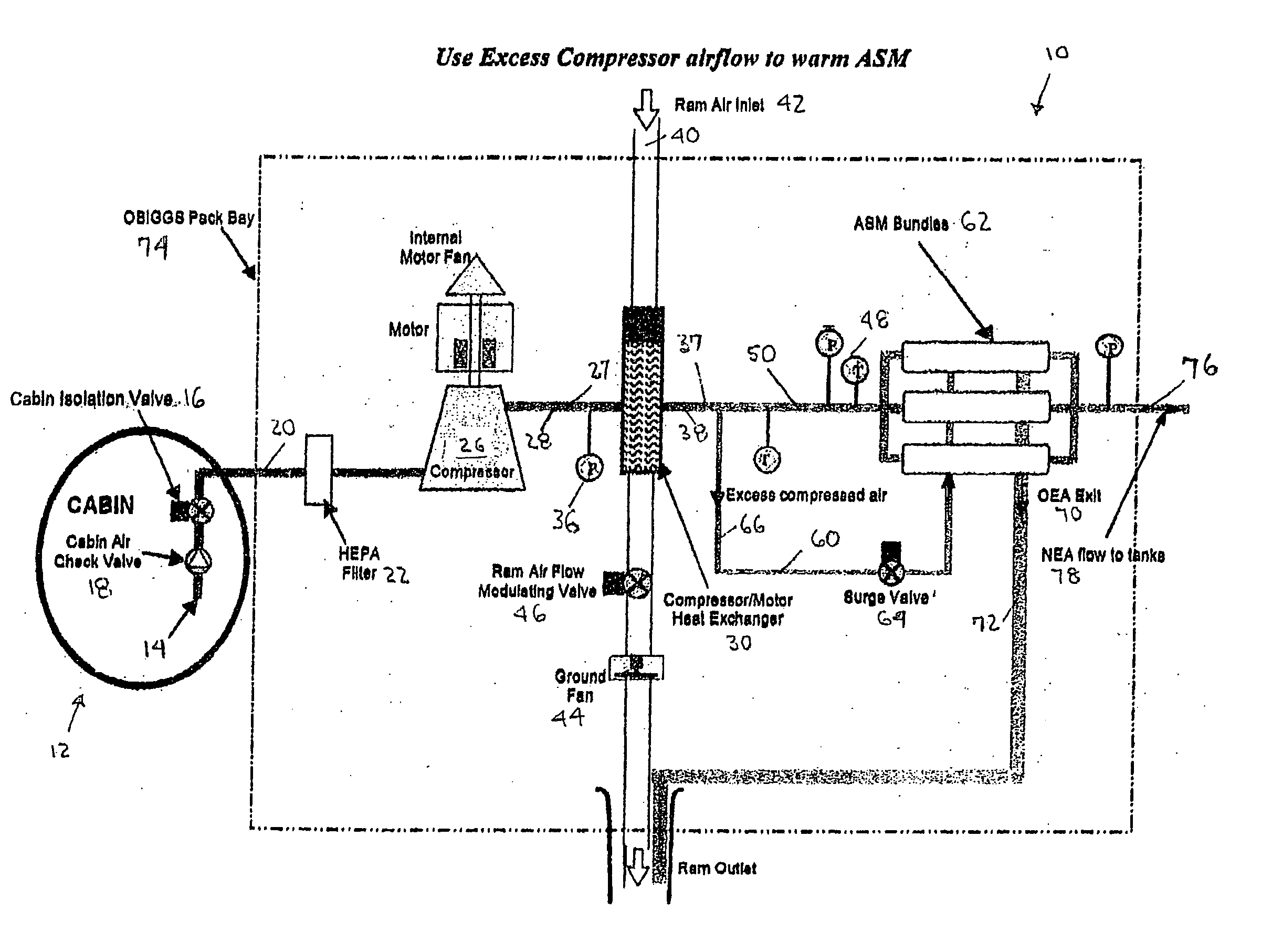
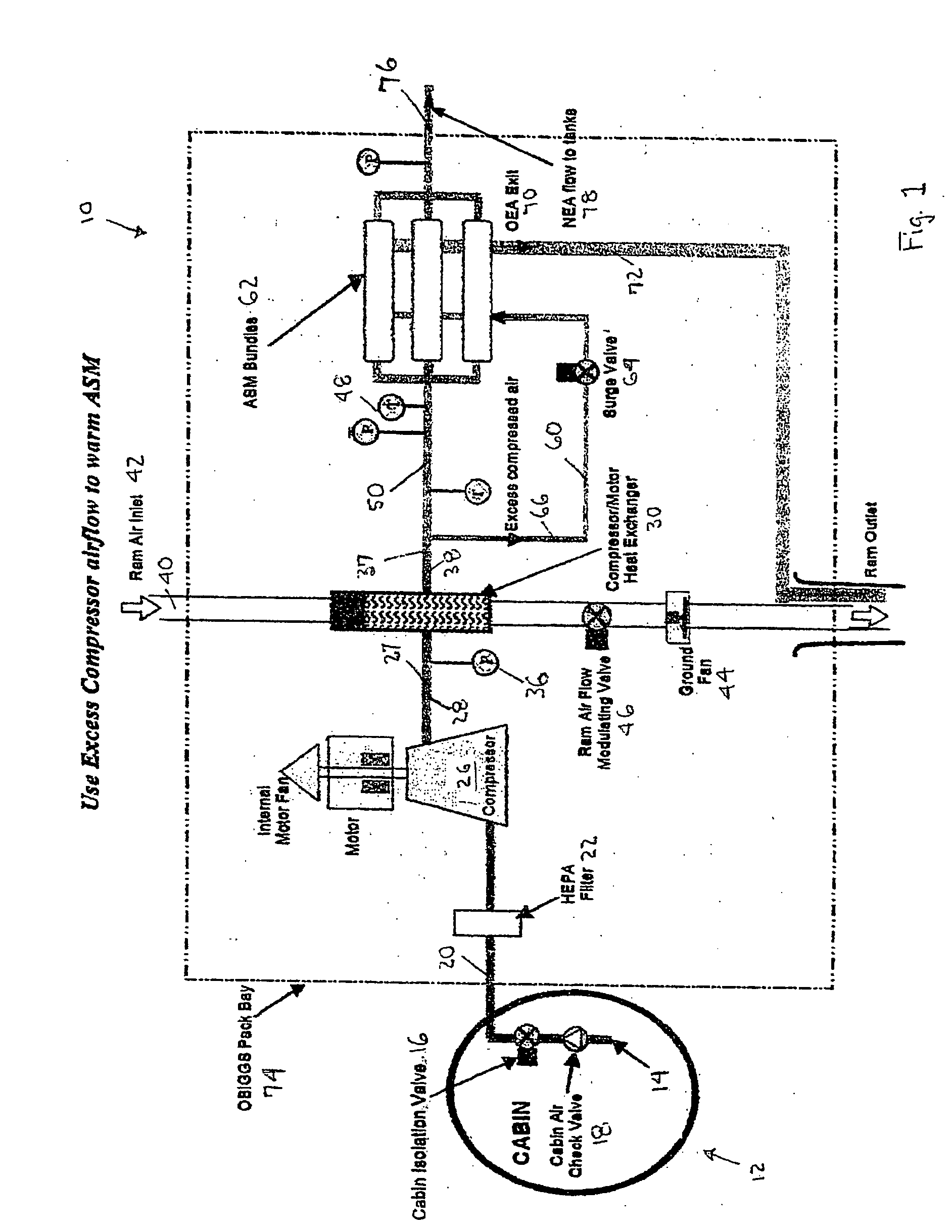
[0029] Referring now to the several drawings, and particularly to FIG. 1, schematically depicted therein is a first embodiment 10 of an OBIGGS that utilizes excess or surplus compressor airflow to warm an ASM. Specifically, when the aircraft is to initiate the operation of OBIGGS, a cabin isolation shut-off valve 16 is commanded to open. At the same time, a motor driven radial flow centrifugal compressor 26 is actuated to draw cabin air 14, via inlet line 20 and cabin air check valve 18, from aircraft cabin 12. A compressor motor controller (not shown) commands the motor 52 to operate at variable...


PUM


Abstract

Improvements in aircraft on-board inert gas generating systems wherein generally excess or surplus compressed airflow from a radial flow centrifugal compressor, produced in order to keep the compressor from surging in predetermined “reduced speed/reduced pressure ratio” operating modes, is utilized for at least one of driving a turbofan for conditioning the air separator module inlet air, or warming up/heating an air separator module in the inert gas generating system, thereby utilizing at least some, of the energy of this excess/surplus compressed air that would otherwise be wasted. Several preferential operational methods and structural systems are set forth.

Description


Claims


Application Information

Patent Timeline
Owner PARKER INTANGIBLES LLC
Why Eureka
Try Eureka