Water treatment system having upstream control of filtrate flowrate and method for operating same

Inactive Publication Date: 2005-10-13
BEST GRAHAM J +3
View PDF4 Cites 11 Cited by
  • Summary
  • Abstract
  • Description
  • Claims
  • Application Information

AI Technical Summary

Benefits of technology

[0007] In general terms, a generally constant feed water flowrate, or feed water flowrate less retentate flowrate if there is any retentate removal during permeation, is provided to each membrane filtration unit. A filtrate is withdrawn from each membrane filtration unit by applying a generally constant suction to each membrane filtration unit. After commencing operation of the system, a generally constant equilibrium filtrate flowrate is established for each membrane filtration unit although the permeability of the membranes decreases over time (due to membrane fouling and/or an increase in the viscosity of the feed water). In order to maintain a generally constant flux across the membranes for each membrane filtration unit, the pressure on the upstream or feed side of each membrane unit is automatically increased as required. This increase in upstream pressure is accomplished by continuing to supply feed water at a rate equal to the desired filtrate flowrate and allowing the liquid head, or depth of water, above the membrane filtration units to increase as required until the liquid head provides enough pressure to provide the desired filtrate flowrate. The maintenance of a generally constant flux across the membranes for each membrane unit results in a generally constant filtrate flowrate from each membrane filtration unit. The available tank freeboard above each membrane filtration unit is designed to allow for a maximum liquid head calculated based on a “worst case” scenario (i.e., the lowest permeability of the membrane that occurs at the highest feed water viscosity and the highest permitted membrane resistance or fouling). Similarly, the system is designed, primarily by not making the suction on the filtrate side of the membranes too strong, such that flux under the best anticipated conditions does not result in the water level dropping below the highest part of the membranes during ordinary permeation.
[0008] The flowrate of feed water into each unit is independent of the water level in the unit and,

Problems solved by technology

The inventors have noticed that, while it is desirable to have an overall constant filtrate flowrate from a membrane system and similar flow rates between parallel filtration units, having sensors and controlled devices on the downstream or filtrate (permeate) side of each membrane filtra

Method used


Image

  • Water treatment system having upstream control of filtrate flowrate and method for operating same
  • Water treatment system having upstream control of filtrate flowrate and method for operating same

Examples


Example

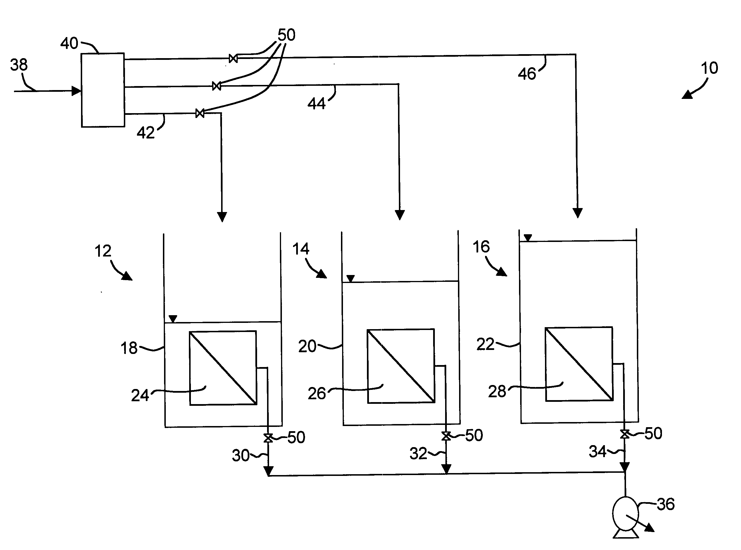
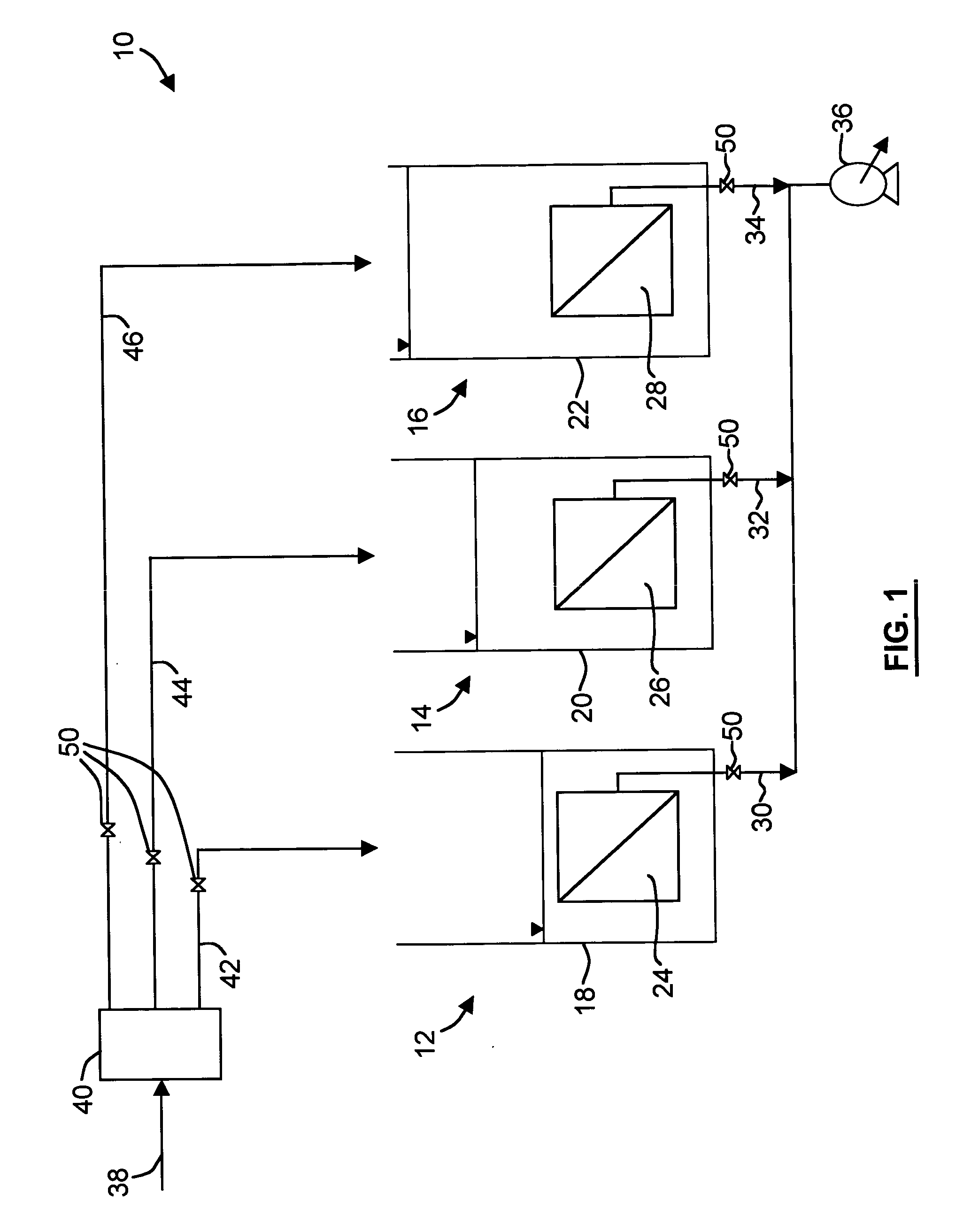
[0011] Referring first to FIG. 1, a water treatment system according to an embodiment of the present invention is shown generally at 10. The water treatment system 10 has, in the embodiment illustrated, three membrane filtration units 12, 14, 16 although there may be other numbers of filtration units, for example between 1 and 10. Untreated feed water flows through a main feed water line 38 towards a flow regulating means 40, for example, a series of weirs of the same shape and elevation on the down-stream edge of a splitter box, to ensure a generally constant flowrate of untreated feed water to each membrane filtration unit 12, 14, 16 through separate feed lines 42, 44, 46, respectively. Each filtration unit 12, 14, 16 has a tank 18, 20, 22 and one or more membrane modules 24, 26, 28, respectively. Filtrate (filtered water or permeate) is removed from each membrane module 24, 26, 28 through separate filtrate lines 30, 32, 34, respectively, which may be connected to a source of suct...


PUM

PropertyMeasurementUnit
Pressureaaaaaaaaaa
Flow rateaaaaaaaaaa
Shapeaaaaaaaaaa

Abstract

A method for treating water with a membrane filtration unit provides a generally constant filtrate flowrate from one or more membrane filtration units by varying the pressure on the upstream or feed side of the unit(s) as required by changes in the permeability of the (units).

Description

[0001] This is an application claiming the benefit under 35 USC 119(e) of U.S. Application Ser. Nos. 60 / 560,614, filed Apr. 9, 2004, and 60 / 585,077, filed Jul. 6, 2004. Application Ser. Nos. 60 / 560,614 and 60 / 585,077 are incorporated herein, in their entirety, by this reference to them.FIELD OF THE INVENTION [0002] The present invention relates to water treatment, and more particularly to water treatment using immersed filtering membranes. BACKGROUND OF THE INVENTION [0003] Membrane systems consist of one or more membrane filtration units which may be connected together in parallel. It is desirable to have a substantially constant filtrate flowrate overall and the same filtrate flowrate from each membrane filtration unit. However, the filtrate flowrate from a membrane filtration unit under a constant suction can vary depending on the state of fouling of the membranes. Moreover, similar membrane filtration units do not necessarily become fouled at the same rate. [0004] Accordingly, i...

Claims


Application Information

Patent Timeline
IPC IPC(8): B01D61/14B01D61/18B01D61/20B01D61/22C02F1/00C02F1/44
CPCB01D61/142B01D61/18B01D61/22C02F1/008C02F1/444C02F2301/043B01D61/146
Inventor BEST, GRAHAM J.ADAMS, NICHOLAS WILLIAM HARCSARCOTE, PIERRE LUCIENZABARYLO, DANIEL RICHARD
Owner BEST GRAHAM J
Why Eureka
Try Eureka