Molded parts with discontinuous fabric surface areas and processes for their production

a technology of discontinuous fabric and molded parts, which is applied in the direction of weaving, other domestic articles, woodworking apparatus, etc., can solve the problems of affecting the quality of molded articles, and unable to eliminate secondary operations, so as to achieve fast and efficient process, prevent fabric material damage, and improve quality

Inactive Publication Date: 2005-10-13
MARCHBANKS ERIC L +6
View PDF22 Cites 4 Cited by
  • Summary
  • Abstract
  • Description
  • Claims
  • Application Information

AI Technical Summary

Benefits of technology

[0006] The present invention thus provides a better fabric-laminated plastic part and a novel process and part design where a high quality, precisely located, smooth fabric surface is provided in a fast and efficient process. The fabric can be selected from a wide range of fabric types and laminated to the support layer. The fabric laminate is then precut, stamped and / or otherwise shaped to desired size. The laminated fabric piece is inserted into a mold cavity by hand or any generally known mechanical / robotic means and is adhered to plastic substrate component that is injected into the mold cavity to provide a fabric-laminated piece for further process steps or assembly to a finished product with an aesthetically pleasing and durable fabric covering. Proper selection of the combination of the support layer material, the plastic substrate material and the fabric provides the necessary processability and rigidity to prevent the fabric material from damage or distortion during the molding process and sufficient adhesion to resist delaminating or peeling off the molded part during use.

Problems solved by technology

However, none of the prior art references teach an efficient and effective technique for preparing thin-wall, molded articles that have precisely located fabric surfaces with smooth fabric surface areas that are intended to have discontinuities, voids or openings (i.e., non-linear fabric edges) corresponding to discontinuities, voids or openings in the underlying molded plastic article.
Instead, the fabric surface areas resulting from these methods tend to be wrinkled and / or require subsequent process steps to provide the voids or openings in the fabric and / or the underlying plastic article.
In addition, none of the prior art references teach a method for precisely locating fabric in a finished molded article as to eliminate the need for secondary operations.
The problems with the fabric surfaces are especially pronounced in low modulus, elastic fabrics that are more easily stretched or compressed in molding step(s).

Method used


Image

  • Molded parts with discontinuous fabric surface areas and processes for their production
  • Molded parts with discontinuous fabric surface areas and processes for their production

Examples


examples

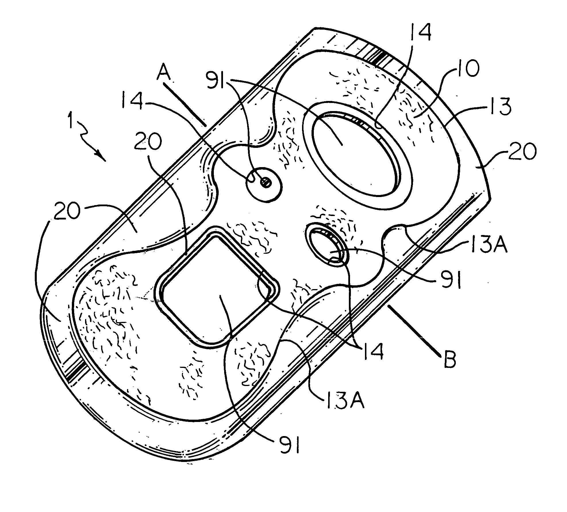
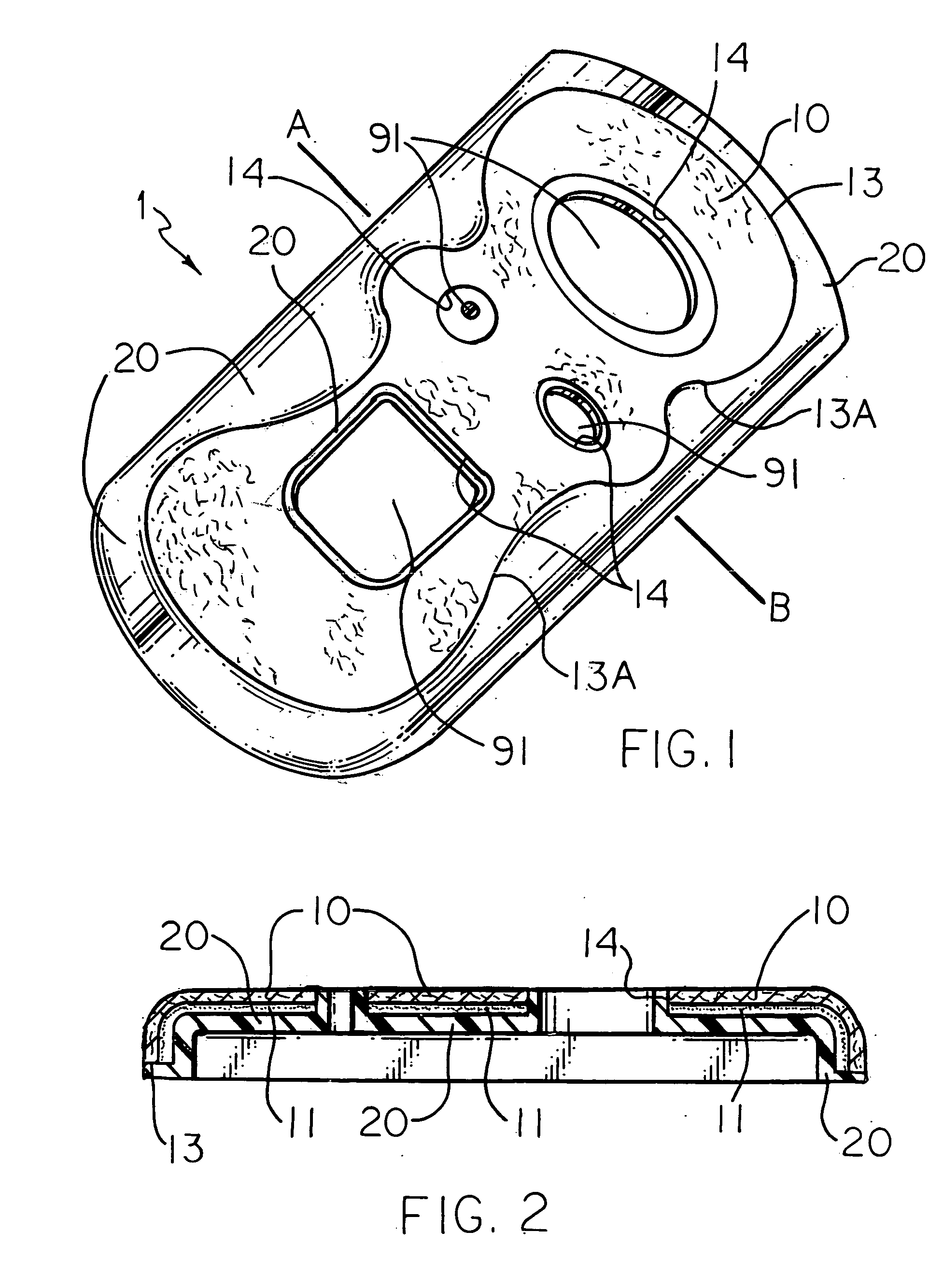
[0025] A part according to the present invention as generally shown in FIG. 1 was designed and produced as follows. A non-woven polyester fabric was laminated to a polycarbonate film 0.005 inches (approx. 0.13 mm) thick by the use of a thermally initiated ethylene vinyl acetate (EVA) adhesive film commercially available from The Dow Chemical Company as Integral 801 brand film. The lamination was conducted at 220 degrees C. (set-point temperature for heating the rolls) on a two-roll laminator. The resulting laminate was pre-cut to the desired size and shape (including internal openings) and inserted into the desired location between the cavity and the core on an injection mold. Placement required careful alignment such that the fabric openings and their edges aligned with the mold surfaces where there would be openings and peripheral fabric edges aligned with their desired locations. The desired fabric front surface is placed against the cavity and held in place by the use of vacuum....


PUM

PropertyMeasurementUnit
densitiesaaaaaaaaaa
densitiesaaaaaaaaaa
thicknessaaaaaaaaaa

Abstract

The present invention thus provides a fabric-laminated plastic part and a novel process where the fabric that provides the surface is pre-laminated with a support layer and supplied into a molding process where a plastic substrate component is molded. The fabric surface piece is precisely located and securely bonded by selection of a support layer plastic material having sufficient heat resistance and/or thickness to sufficiently resist melt softening and stretching during the molding process. This process and fabric laminated plastic article are especially suited for preparing thin-wall, articles that need to have precisely located, smooth fabric surface areas corresponding to discontinuities, voids or openings in the underlying molded plastic article.

Description

[0001] This invention relates to injection molded plastic parts having fabric surface areas in or around areas where there are discontinuities (e.g., voids, openings, contours and the like) at the surface of the part. The molded plastic enclosures of many types of articles need to have openings, gripping surfaces and similar sorts of discontinuous surface areas for purposes of key pads, buttons, switches, displays, aesthetics, etc. This invention provides such parts with an attractive and sturdy fabric surface and a process for making these parts where the fabric edges are precisely located and secured in a very effective and aesthetically pleasing manner. Parts are produced with good appearance, precise dimensions, thin part cross section and stable, secure fabric edge coverings. BACKGROUND OF THE INVENTION [0002] There are a number of processes for providing a surface layer of a fabric, such as leather or simulated leather, onto all or part of the surface of molded plastic parts. ...

Claims


Application Information

Patent Timeline
Patent Type & Authority Applications(United States)
IPC IPC(8): B29C33/12B29C45/14B29C45/16B29K69/00B29K105/20B29L9/00
CPCB29C45/1418B29C45/14344B29C45/14811B29C2045/14237B29K2711/08B29K2713/00B29K2715/003B29K2715/006Y10T442/3325Y10T442/674Y10T442/647Y10T442/3854B29C45/14B29C45/16
Inventor MARCHBANKS, ERIC L.PETERSON, CURL E.DEMINT, TODD A.KINNUNEN, ARI P.BENNICK, KENNETH T.VAN CONETT, THOMAS E.HUS, MICHAEL E.
Owner MARCHBANKS ERIC L
Why Eureka
Try Eureka